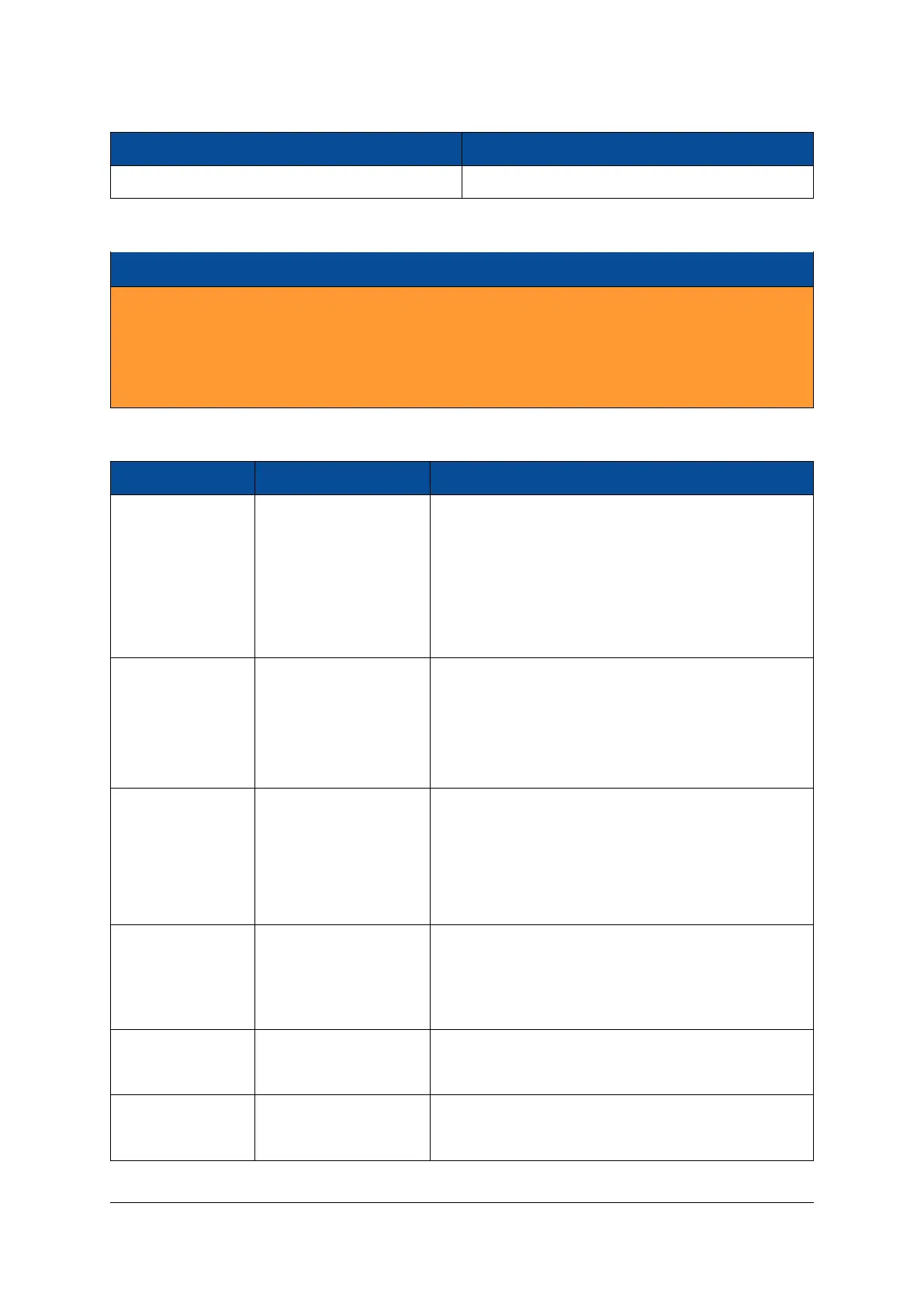
Type Manufacturer
DF40C-30DP-0.4V(51) Hirose
Table 35: Debug Connector Type
Warning!
The Hirose debug connector on the Mercury+ XU1 SoC module is not polarized. Special care must be
taken when connecting the breakout board to the debug connector.
Connecting an external board the wrong way round on the debug connector may damage the equipped
MPSoC device, as well as other devices on the Mercury+ XU1 SoC module.
Table 36 describes the signals routed to the debug connector (valid only for modules revision 1 and 2).
Pin Number Signal Name Description
1 EMMC_IO2_PJTAG_TMS PJTAG TMS
3 I2C_INT#_PJTAG_TCK PJTAG TCK
7 EMMC_IO0_JTAG_TDI PJTAG TDI
9 EMMC_IO1_PJTAG_TDO PJTAG TDO
2 PJTAG_EN# PJTAG enable (enable PJTAG boot mode)
5, 20, 31, 32, 33, 34 GND Ground
10 VCC_3V3
11 VCC_CFG_MIO
21 VCC_ 1V8
4 PS_SRST# PS system reset
6 PS_PROG# Configuration block reset (Refer to Zynq UltraScale+
MPSoC Technical Reference Manual [19])
8 PS_INIT# Initialization completed (Refer to Zynq UltraScale+ MP-
SoC Technical Reference Manual [19])
12 PS_ERROR PS_ERROR_OUT status signal (Refer to Zynq UltraScale+
MPSoC Technical Reference Manual [19])
14 PS_STATUS PS_ERROR_STATUS (Refer to Zynq UltraScale+ MPSoC
Technical Reference Manual [19])
13 I2C_SCL
I2C bus signals
15 I2C_SDA
17 PS_LED1#_UA1RX
Debug UART signals, LED signals
19 PS_LED0#_UA1TX
Continued on next page...
D-0000-428-001 47 / 66 Version 13, 15.08.2019
 Loading...


