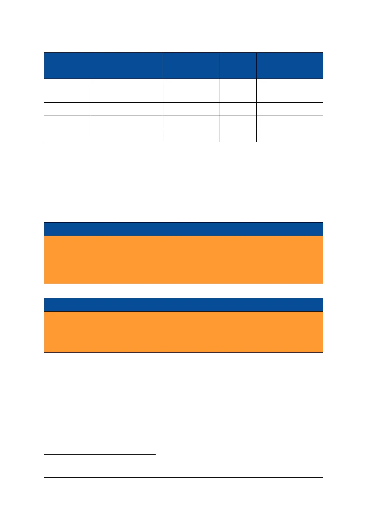
Signal Name MPSoC Pins Supported Connector Connector
Voltages A Pins B Pins
VCC_CFG_MIO VCCO_PSIO1_501,
VCCO_PSIO3_503
1.8 V - 3.3 V ±5% 74, 77 -
VCC_IO_B66 VCCO_66 1.0 V - 1.8 V ±5% - 64, 67, 88, 95, 140, 143
VCC_IO_BN VCCO_N
2
1.2 V - 3.3 V ±5%
3
38 -
VCC_IO_BO VCCO_O
2
1.2 V - 3.3 V ±5%
3
41 -
Table 9: VCC_IO Pins
3
On module connector C there are no VCC_IO pins available, as the signals routed to this connector belong
to FPGA banks which are powered by fixed voltages generated on the module. Note that the VCC_IO pins
on connector C are used on other Enclustra modules; for compatibility purposes it is acceptable to power
these pins even if they are not used on the Mercury+ XU8 SoC module.
The Mercury+ XU8 SoC module may be used in combination with base boards having only two module
connectors.
Warning!
Use only VCC_IO voltages compliant with the equipped MPSoC device; any other voltages may dam-
age the equipped MPSoC device, as well as other devices on the Mercury+ XU8 SoC module.
Do not leave a VCC_IO pin floating, as this may damage the equipped MPSoC device, as well as other
devices on the Mercury+ XU8 SoC module.
Warning!
Do not power the VCC_IO pins when PWR_GOOD and PWR_EN signals are not active. If the module
is not powered, you need to make sure that the VCC_IO voltages are disabled (for example, by using a
switch on the base board, which uses PWR_GOOD as enable signal). Figure 10 illustrates the VCC_IO
power requirements.
2
For HD I/O banks generic supply names are used - refer to Section 2.9.4 for details on I/O banks connectivity and supplies.
3
For voltages of 3.3 V for VCC_IO_BN and VCC_IO_BO the tolerance range is -5% to +3%.
D-0000-454-001 21 / 60 Version 06, 18.11.2019

 Loading...


