USB1_RST#_ETH1_RST is pulled to GND via a 1 kΩ resistor; to release the USB PHY from reset, this signal
must be driven high from MIO23. ETH1_RST# is pulled to 1.8 V via a 10 kΩ resistor; if USB1_RST#_ETH1_RST
signal is driven high from the PS, the Ethernet reset is connected to GND.
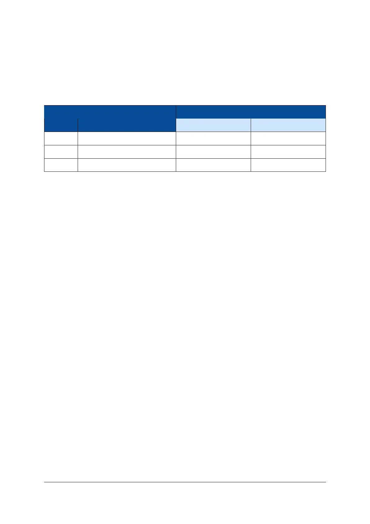
Both reset signals (for Ethernet and USB) are pulled to GND if the PS_POR# is active. Table 31 describes the
behavior of the USB1/ETH1 selection circuit; the default selection is marked in bold.
Condition Function
PS_POR# USB1_RST#_ETH1_RST (MIO23) USB PHY 1 Ethernet PHY 1
0 - In reset In reset
1 0 In reset Active
1 1 Active In reset
Table 31: USB1/ETH1 Selection
The two Gigabit Ethernet PHYs have a shared MDIO interface and a shared interrupt line. The interrupt
output of the Ethernet PHYs is connected to the I2C interrupt line, available on MIO pin 12.
2.20.3 External Connectivity
The Ethernet signal lines can be connected directly to the magnetics. Please refer to the Enclustra Module
Pin Connection Guidelines [10] for details regarding the connection of Ethernet signals.
2.20.4 MDIO Address
The MDIO interface is shared between the two Gigabit Ethernet PHYs - these can be configured using the
corresponding address. The MDIO address assigned to PHY 0 is 3 and to PHY 1 is 7.
The MDIO signals are mapped to MIO pins 76-77 and they are routed directly to PHY 1 and via a level shifter
to PHY 0.
2.20.5 PHY Configuration
The configuration of the Ethernet PHYs is bootstrapped when the PHYs are released from reset. Make sure all
I/Os on the RGMII interface are initialized and all pull-up or pull-down resistors are disabled at that moment.
The bootstrap options of the Ethernet PHYs are set as indicated in Table 32.
D-0000-454-001 40 / 60 Version 06, 18.11.2019

 Loading...


