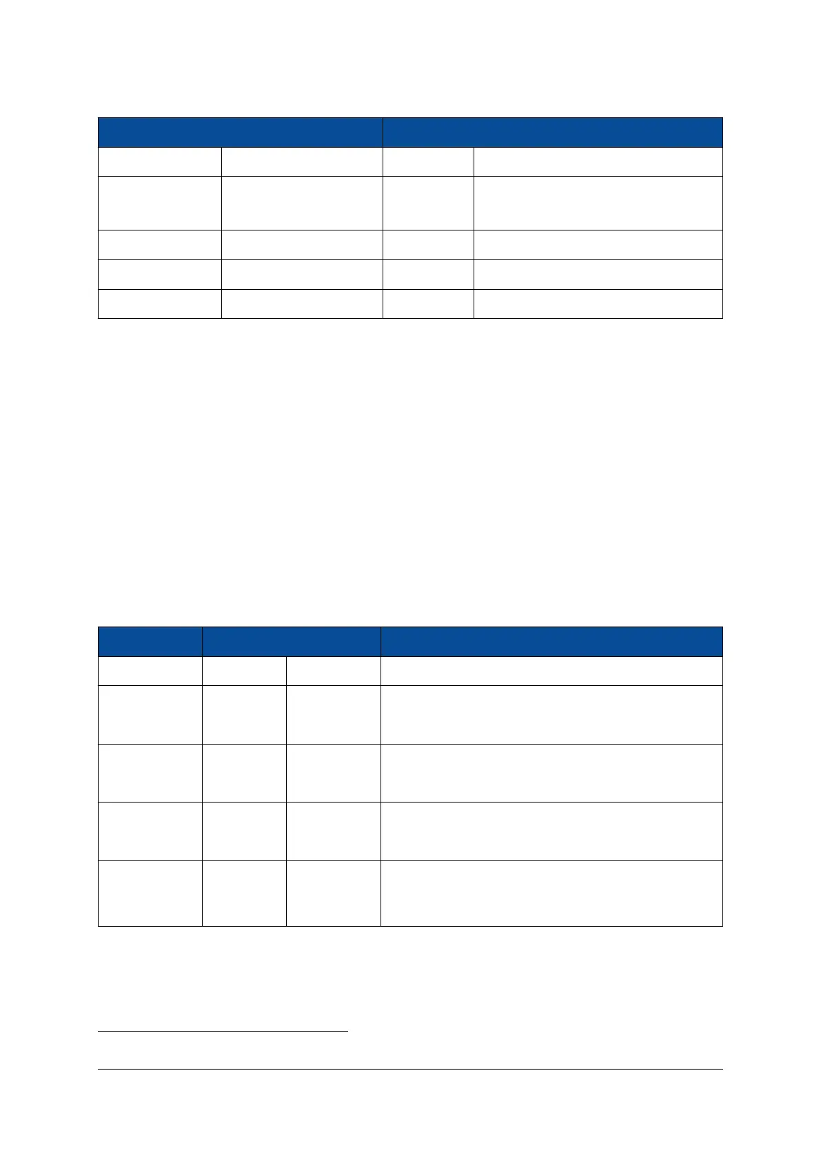
Pin Name Module Connector Pin Connection Description
VMON_INT A-102 VCC_INT PL core voltage
VMON_VTT_VBAT B-8 VCC_VTT DDR termination voltage (default)/MP-
SoC battery voltage (assembly option)
VMON_PSINT B-168 VCC_PSINT PS core voltage
VMON_0V9 B-167 VCC_0V9 0.9 V on-board voltage
VMON_1V2
10
C-8 VCC_1V2 1.2 V on-board voltage
Table 19: Voltage Monitoring Outputs
10
2.12 Clock Generation
A 33.33 MHz oscillator is used for the Mercury+ XU8 SoC module clock generation; the 33.33 MHz clock
is fed to the PS. A 100 MHz LVDS oscillator is connected to FPGA bank 65 and can serve as a reference for
the PLL used to generate the clocks required for the PL DDR interface. The signal is terminated with a 100
Ω parallel resistor close to the FPGA pins. The same 100 MHz clock is used as a reference clock input for PS
GTR bank 505.
A 27 MHz CMOS oscillator provide a reference clock input to the PS GTR bank 505. A 24 MHz clock and a
25 MHz clock are used for the USB PHYs and Ethernet PHYs respectively. The crystal pads for the MPSoC
RTC are connected to a 32.768 kHz oscillator on the Mercury+ XU8 SoC module.
Table 20 describes the clock connections to the MPSoC device.
Signal Name Frequency Package Pin MPSoC Pin Type
CLK33 33.33 MHz P19 PS_REF_CLK
GTR_CLK27_P
27 MHz
H23 PS_MGTREFCLK3P_505
GTR_CLK27_N H24 PS_MGTREFCLK3N_505
GTR_CLK100_P
100 MHz
K23 PS_MGTREFCLK2P_505
GTR_CLK100_N K24 PS_MGTREFCLK2N_505
CLK100_P
100 MHz
AH6 IO_L13P_T2L_N0_GC_QBC_65
CLK100_N AJ6 IO_L13N_T2L_N1_GC_QBC_65
PS_PADI
32.768 kHz
M21 PS_PADI (crystal pad input for MPSoC built-in RTC)
PS_PADO N21 PS_PADO (crystal pad output for MPSoC built-in RTC)
Table 20: Module Clock Resources
10
Voltage monitoring output available on the module connector starting with revision 2 modules.
D-0000-454-001 31 / 60 Version 06, 18.11.2019

 Loading...


