PHY Type Manufacturer Type
USB3320C Microchip USB 2.0 PHY
Table 34: USB 2.0 PHY Type
2.21.2 Signal Description
The ULPI interface for the PHY 0 is connected to MIO pins 52-63 for use with the integrated USB controller.
The ULPI interface for the PHY 1 is connected to MIO pins 64-75. The MIO signals are shared between
Ethernet PHY 1 and USB PHY 1, therefore only one of them can be used. By default the Ethernet connection
is enabled. Please refer to Section 2.20.2 for details on how to select Ethernet or USB mode.
Warning!
USB 1 interface is not available when Gigabit Ethernet 1 interface is active.
2.22 USB 3.0
Xilinx Zynq Ultrascale+ devices feature two built-in USB 3.0 controllers and PHYs, configurable as host or
device. The PHY interface used by the USB 3.0 controller is PIPE3, supporting a 5 Gbit/sec data rate in host
or device modes. The interface of each USB 3.0 controller uses one of the PS GTR lanes.
A 100 MHz differential clock is available on the module and connected to PS_MGTREFCLK2 pins, to be used
as a reference clock for the USB 3.0 interface. It is also possible to provide another reference clock from the
base board to the MGTPS_REFCLK* pins.
Details on the built-in USB 2.0/3.0 controller and on the usage of the PS GTR lanes are available in the Zynq
UltraScale+ MPSoC Technical Reference Manual [18] and in the Zynq UltraScale+ MPSoC Overview [22].
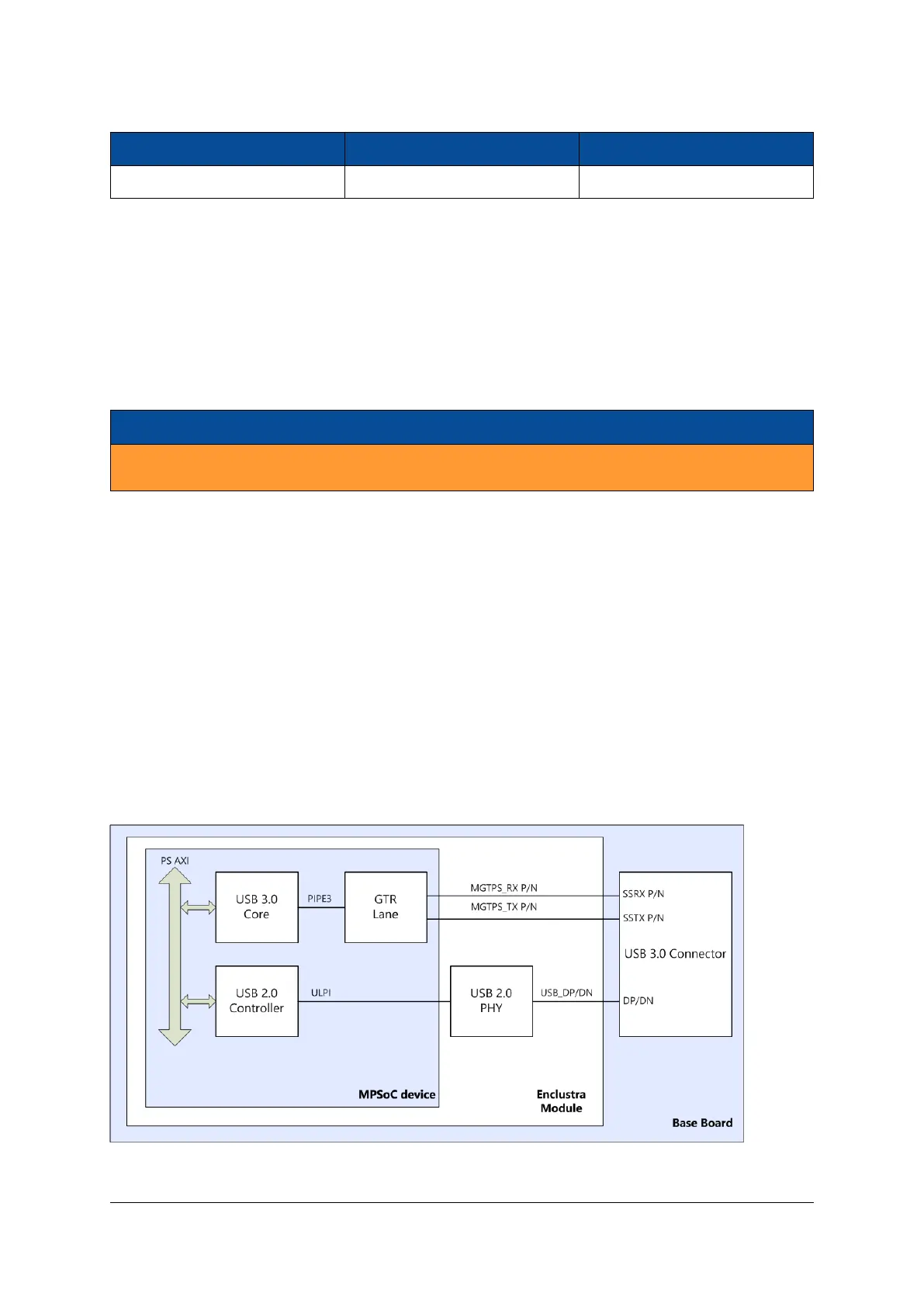
Figure 11 shows an example of a USB 3.0 implementation using the built-in Xilinx USB 3.0 interface and the
USB 2.0 signals from the PHY, all routed to a USB 3.0 connector on the base board.
Figure 11: USB 3.0 Implementation Example
D-0000-454-001 42 / 60 Version 06, 18.11.2019

 Loading...


