must be connected to GND. The dedicated channel is not available on the module connector.
The analog input signals can be connected to any normal I/O FPGA bank, provided that all analog pins
belong to the same bank. Note that the HD I/O banks have a limited number of analog inputs and they
must be connected directly to the SYSMONE4 primitive instead of to the Xilinx System Management Wizard
IP core.
For detailed information on the ADC and system monitor, refer to the UltraScale Architecture System Monitor
document [19], Zynq UltraScale+ MPSoC Technical Reference Manual [18] and System Management Wizard
Product Guide [21].
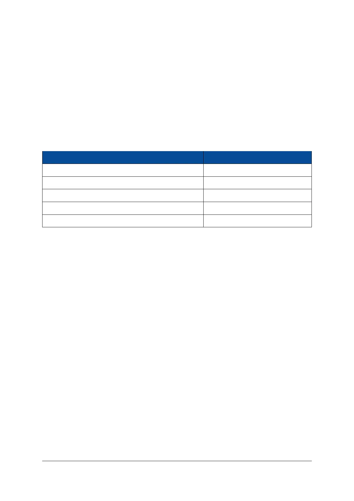
Table 11 presents the ADC Parameters for the PL System Monitor. The PS System Monitor is only used for
monitoring the on-chip power supply voltages and die temperature.
Parameter Value (PL Sysmon)
VCC_ADC 1.8 V
VREF_ADC Internal
ADC Range 0-1 V
Sampling Rate per ADC 0.2 MSPS
Total number of channels available on the module connector 16 (only auxiliary inputs)
Table 11: System Monitor (PL) Parameters
2.10 Multi-Gigabit Transceiver (MGT)
There are two types of multi-gigabit transceivers available on the Mercury+ XU8 SoC module: GTH transceivers
(connected to the PL) and GTR transceivers (connected to the PS).
GTH Transceivers
There are 16 GTH MGTs available on the Mercury+ XU8 SoC module organized in four FPGA banks - Table
12 describes the connections.
The GTH banks are numbered differently depending on the MPSoC device equipped on the module:
• MGT bank A represents:
• GTH bank 223 for ZU4/ZU5 devices
• GTH bank 224 for ZU7 devices
• MGT bank B represents:
• GTH bank 224 for ZU4/ZU5 devices
• GTH bank 225 for ZU7 devices
• MGT bank C represents:
• GTH bank 225 for ZU4/ZU5 devices
• GTH bank 226 for ZU7 devices
• MGT bank D represents:
• GTH bank 226 for ZU4/ZU5 devices
• GTH bank 227 for ZU7 devices
D-0000-454-001 24 / 60 Version 06, 18.11.2019

 Loading...


