27
Manual: Transport, Installation and Start-Up: DC CompactCharger ECC 320 ©EnerCharge GmbH
ELECTRICAL INSTALLATION ECC 320
7.6.2 Connection Data for Cable Entry Plate
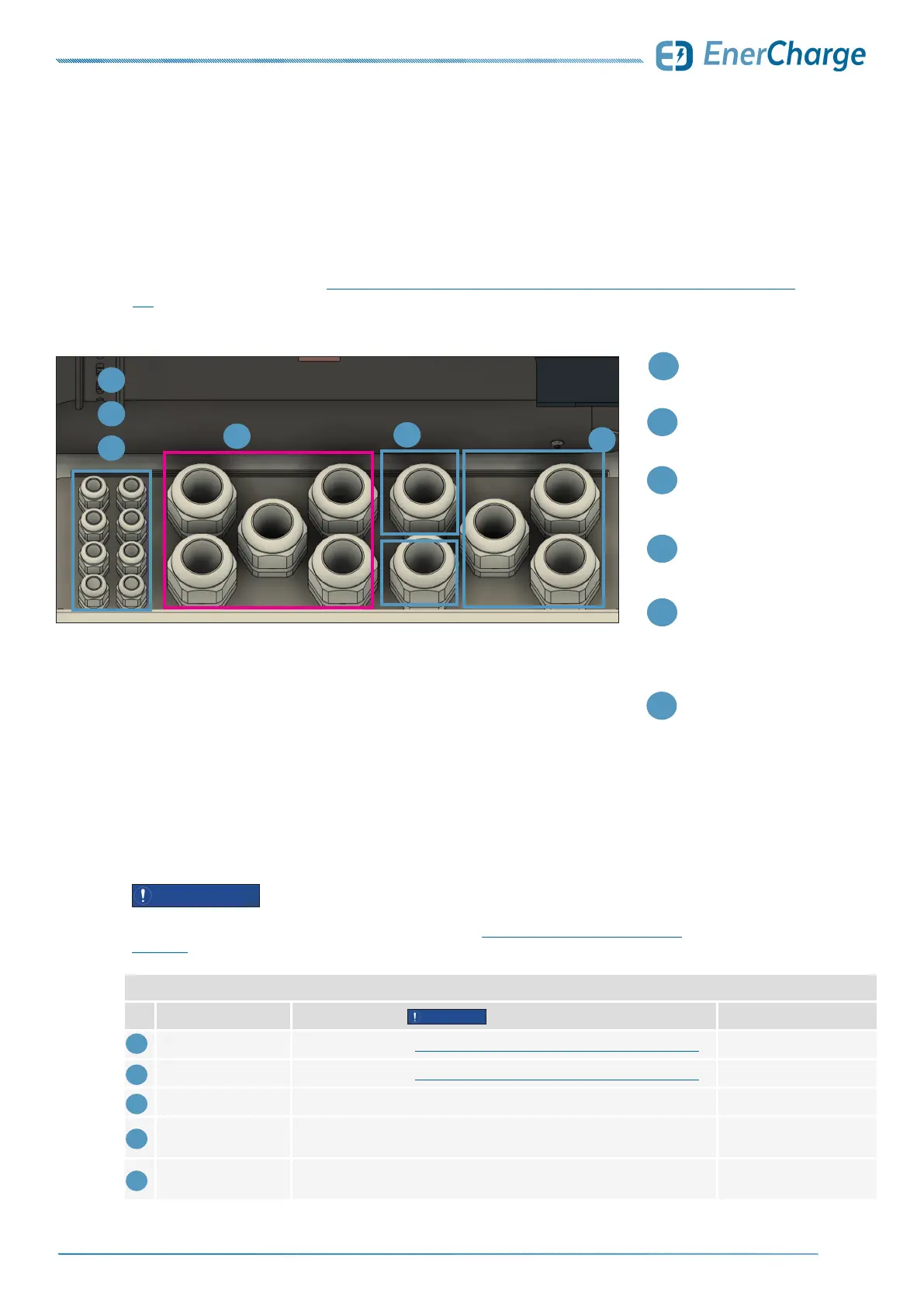
The cables used must be inserted into the housing through the cable entry plate as shown
in the illustration. Section „7.7.1 Overview of the Electrical Connection for the ECC 320“ on page
28 gives an overview of the electrical installation.
2
Entry for
PE-N: conductor AC
1
6
Entry for
AC (400 V) supply line
Optional:
When using
aluminum
conductors
2
1
3
3
Entry for
LAN Control (WAN)
4
5
Optional:
Modbus RTU
(connection AC-Charger)
Optional:
LAN
(for load management or
connection of AC wallboxes
e.g. KEBA)
4
5
6
Fig. 28: Cable assignment on cable entry plate
Connection Data of Cable Entry Plate Single
No. Connection Cable Type Outer Cable Diameter:
1
AC (400 VAC) Dimensioning see: „7.4.1 Cable Cross-Sections of Main AC Supply Line“ on page 23 approx. 27 to 35 mm
2
PE-N: Conductor AC Dimensioning see: „7.4.1 Cable Cross-Sections of Main AC Supply Line“ on page 23 approx. 27 to 35 mm
3
LAN Control (WAN) Ex.: UNITRONIC LAN 1000 S/FTP Cat.7 (L)PE 4x2xAWG23/1 5 to 10 mm
4
Optional:
Modbus RTU
Ex.: UNITRONIC BUS LD 2x 0,22 mm
2
8 to 13 mm
5
Optional: LAN
(Load management,
external wallboxes)
Ex.: UNITRONIC LAN 1000 S/FTP Cat.7 (L)PE 4x2xAWG23/1 5 to 10 mm
7.6.1 Cable Entry Plate
The cable types listed are examples. The cable types used in the installation must be adapted to the
requirements of the particular installation site. See additionally: „7.4 Cable Cross-Sections of AC-Supply“
on page 23.
ATTENTION
ATTENTION
Table 2: Connection data cable entry plate
7.6 Cable Entry