32
Manual: Transport, Installation and Start-Up: DC CompactCharger ECC 320 ©EnerCharge GmbH
ELECTRICAL INSTALLATION ECC 320
After electrical installation, the KEBA wallbox must be congured for use.
Observe the following points during conguration:
> The KEBA Wallbox may only be installed, commissioned and maintained by qualied
electricians in compliance with the applicable national regulations. See: „3.2 Qualification of
Staff“ on page 7.
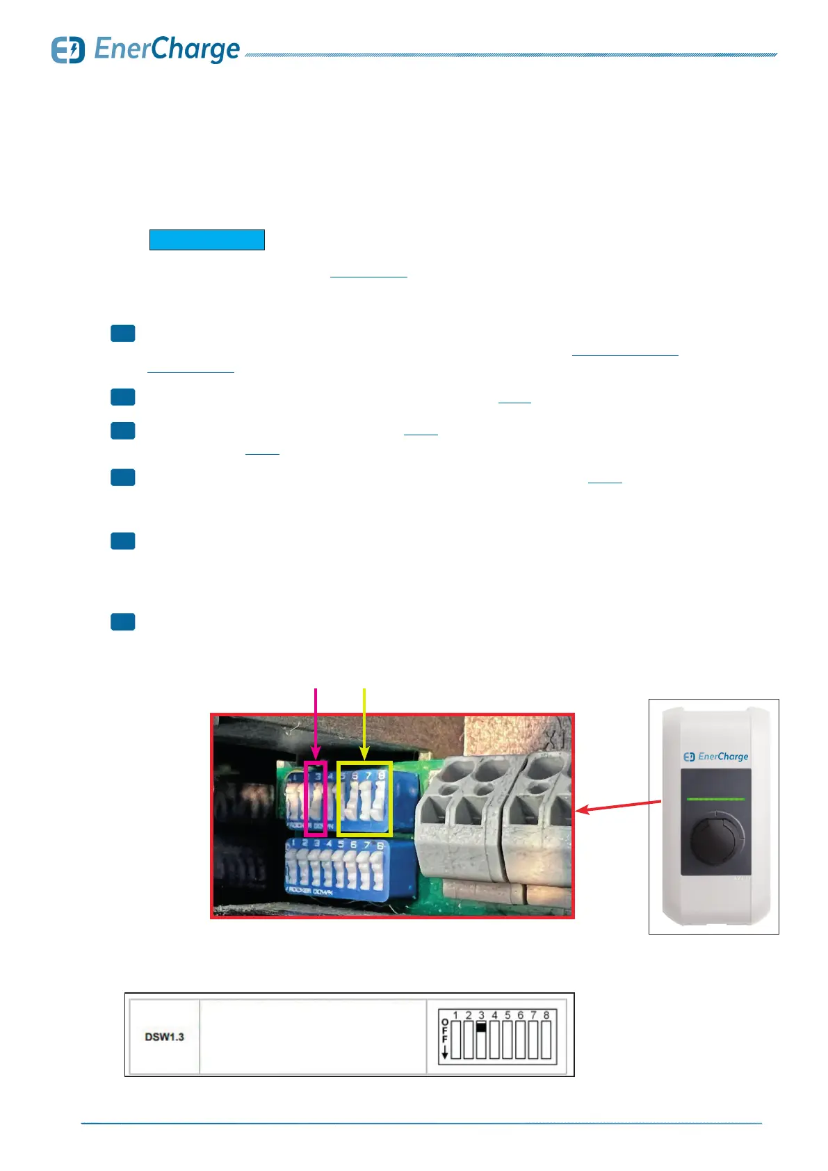
> For correct handling of the DIP switches, be sure to observe Fig. 37.
> Set DIP switch "3" to the "ON" position. See: Fig. 34.
• Additionally see Fig. 35 for more information on DIP-Switch "3".
> Set the maximum charging current (amperes) via DIP switches "6/7/8": see Fig. 37.
• Set the maximum charging current (amps) of the KEBA Wallbox so that it is less than or equal to
the operating current according to the type plate.
> Changes to settings on the DIP switches only take effect after the charging station
has been restarted.
• To restart, press the "Service key" until the first signal tone (approx. 1 second). Alternatively, the
charging station can also be switched off briefly using the circuit breaker.
> Conguration of KEBA wallbox performed successfully.
For the electrical connection of the KEBA wallbox, observe the installation ins-
tructions of the manufacturer KEBA: www.keba.com.
G INFORMATION
Fig. 34: Example of DIP-Switch setting for 32 Ampere (22kW)
Fig. 35: Description of DIP-Switch 3
Fig. 36:
KEBA-Wallbox
DIP-Switch 6/7/8DIP-Switch 3
7.9 Optional: Konfiguration KEBA
1
2
3
4
5
>
Activate UDP or Modbus TCP as communication
protocol. Only available for P30 c-series and
x-series.
For details see "UDP Programmers Guide" or
"Modbus TCP Programmers Guide".