31
Manual: Transport, Installation and Start-Up: DC CompactCharger ECC 320 ©EnerCharge GmbH
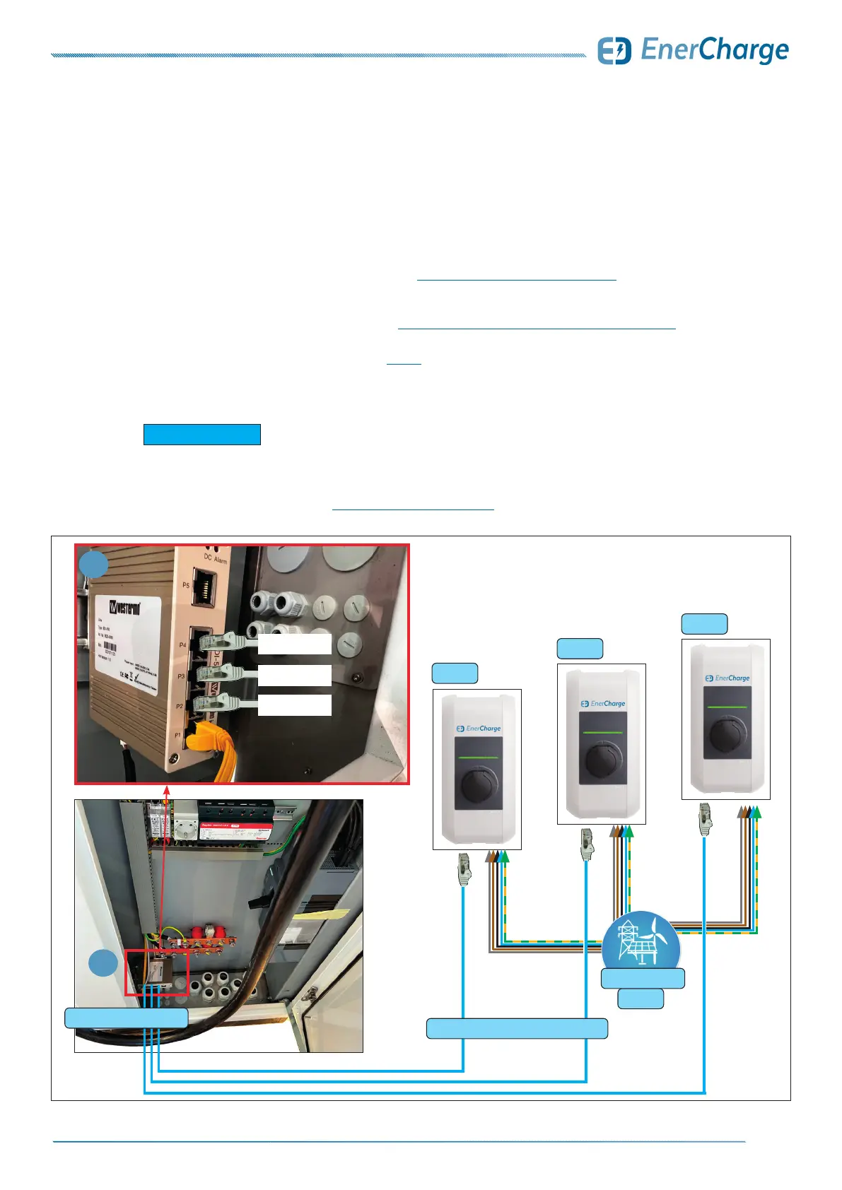
ELECTRICAL INSTALLATION ECC 320
Fig. 33: Ethernet wiring diagram KEBA
KEBA 1
KEBA 2
KEBA 3
1
AC 400V
internal network switch
Cat.6 RJ45: star-shaped wiring
LAN: KEBA 3
LAN: KEBA 2
LAN: KEBA 1
1
energy supplier
7.8 Optional: Connecting a Wallbox via Ethernet
On request (special equipment), external charge points such as wallboxes (e.g.
KEBA) can be connected via Ethernet (RJ45).
The following points must be observed when connecting:
> The ECC320 may only be installed, started up and serviced by qualied electricians in accordance
with the applicable national regulations. See: „3.2 Qualification of Staff“ on page 7.
> A category 6 (Cat.6) Ethernet (RJ45) cable leads from the wallboxes (e.g. KEBA) to the internal
network switch (optional equipment): see „Fig. 33: Ethernet wiring diagram KEBA“ on page 31.
• A Cat.6 Ethernet cable (RJ45) must be used for proper communication.
• The wiring is executed "star-shaped" - see Fig. 33.
• A maximum of 12 external wallboxes can be connected with the internal network switch (special equipment).
• An external network switch is required to connect more than 12 external charge points (12+).
KEBA wallboxes require a category 6 (Cat.6) Ethernet (RJ45) cable.
Up to 12 external charge points (≤12): connection via internal network switch
(special equipment: option must be included in the order).
More than 12 external charge points (+12): an external network switch is required.
Contact EnerCharge for this purpose: „9.8 Customer Service“ on page 50.
G INFORMATION