Checking The Power Supply
POWER SUPPLY VOLTAGE CHECK POINTS
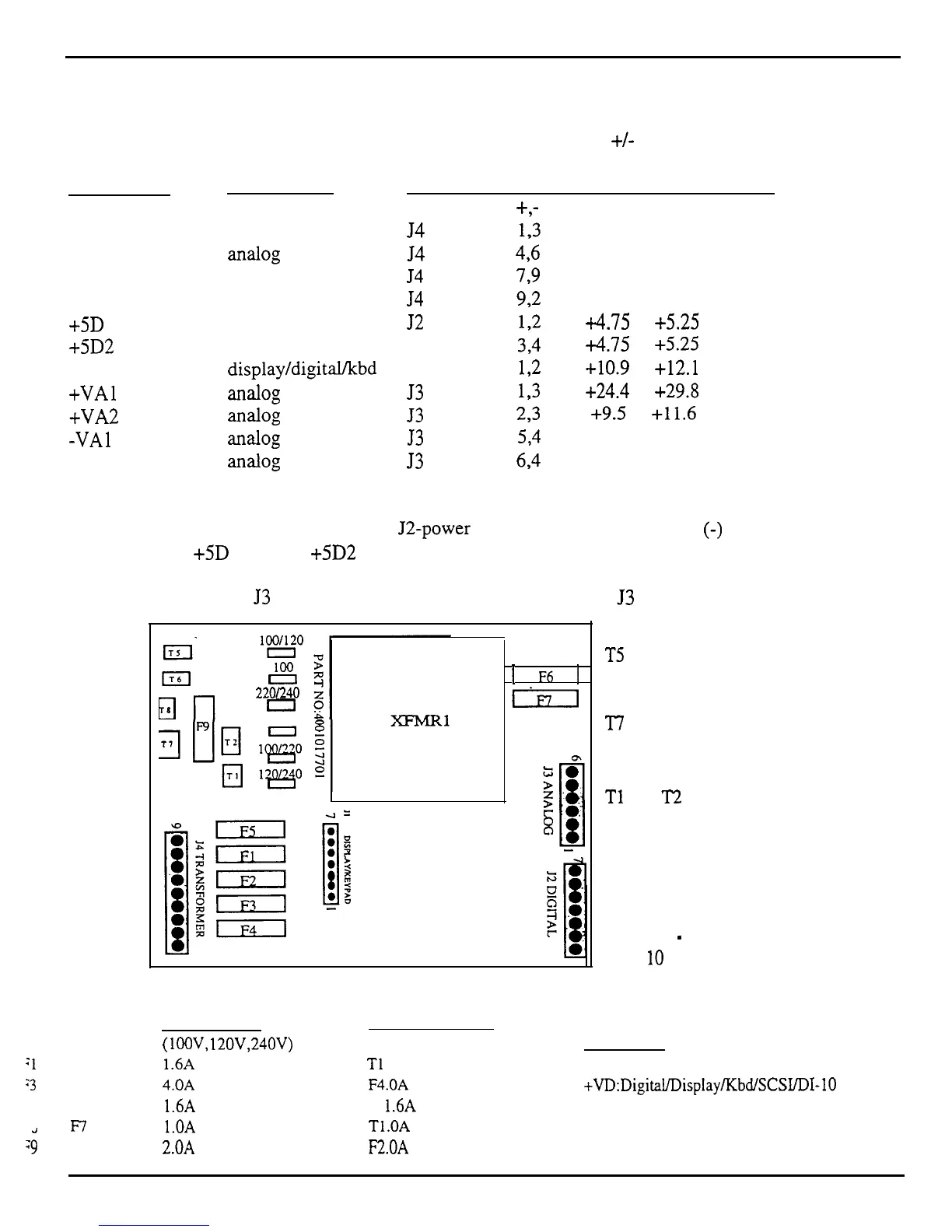
Below are the voltage ranges for proper operation of each fully loaded supply and the pins to read across
with the voltmeter (see Figure 9). It is normal for line voltage to vary +/- 10%.
Designation
Where Used
Connector Pins Allowable range Units
+,-
Digital Supply
digital
54
193
18.7 to 22.8
VACrms
Analog Supply
XXil0g
54
496
17.1 to 20.9
VACrms
Display Filament display
54
799
5.1 to 6.2
VACrms
Display Offset
display
54
92
-25.0 to -30.6
VDC
+5D 1
digital
52
172
i4.75 to
+5.25 VDC
+5D2
digital J2
3-4
+4.75
to
+5.25 VDC
+VD
display/digital/kbd J 1
12
+10.9
to
+12.1 VDC
+VAl LUlal0g
53
193
+24.4
to
+29.8 VDC
+VA2
aIMlog
53
2,3
+9.5
to
+11.6 VDC
-VA1
Wtl0g
53
534
-27.6 to -33.8 VDC
-VA2
TilldOg
53
694
-10.9 to -12.1 VDC
J2 was marked Xl on some early versions of the power supply board. These voltages can also be
measured on the digital board (near the J2-power connector) with the ground
(-)
probe on the digital
board heat sink:
+5D
1 at FB3; +5D2 at FB2; and +VD at FB 1.
On keyboard units, the
53
power supply voltages may be measured at
53
of the analog board.
:l
and F2
:3
and F4
.,
and
F7
29
li%”
El
22OL240
0
120
t
F6
1
Gil
T5 orange
T6 white
T8 blue
‘I7 red
Tl
and
T2
are green
transformer wires
Figure 9
-
ASR-
10
Power Supply Board
UL rated fuses
(lOOV, 12OV,24OV)
1.6A fast blow
4.OA
fast blow
1.6A fast blow
l.OA slow blow
2.OA
fast blow
Fuse Ratings (as of October 1995)
IEC 127 rated fuses
(230V units only)
Where Used
Tl
.OA slow blow Analog
F4.OA
fast blow
+VD:DigitaL/Display/bdfSCWDI-10
F
1.6A
fast blow Display
Tl.OA slow blow
Analog
F2.OA
fast blow
Line Fuse
ASR Service Manual
13
 Loading...


