Revlacina ASR Rack Modules
run dual shielded
cable on top of
ledge
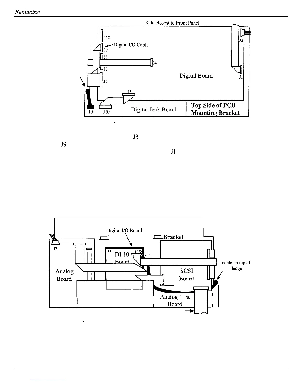
Figure 25
-
Top Side of the ASR-10 Rack PCB Mounting Bracket
6.
Connect the 20-pin ribbon to
53
of the DI-10 board (single bend end) and the other side to
J9
on the digital board (double bend end).
7.
Plug one end of the dual shielded cable onto
Jl
on the DI-10 board. This connector is
keyed so it will only go on one way.
8.
Run the cable down between the DI-10 and SCSI boards. Then turn the cable so that it runs
between the SCSI and analog jack board. Bring the cable up over the cutout on the PCB
Mounting Bracket to the top side of said bracket.
9.
Plug the free end of the dual shielded cable onto J6 of the digital jack board located on the
top side of the PCB Mounting Bracket. This connector is keyed so it will only go on one
way.
Side closest to Front Panel
Mylar Insulator underneath DI- 10
Underside of
PCB Mounting
IIBracket
run dual shielded
OEX-6sr Board
I
mlalog Jac
RCV-Xtrl
SCSI Cable to connector on rear panel
Figure 26
-
Installing a DI-10 Board into an ASR-10 Rack Unit
-
64
ASR Service Manual

 Loading...


