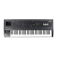
Reulacina ASR-I
O/88
Modules
a) J8
-
20-pin ribbon cable, and
b) J7
-
lo-pin ribbon cable.
5.
Remove the four (4) screws that hold the analog jack board to the I/O bracket.
6.
Lift the left end above the analog bracket and slide the jacks, pot, and switch out of holes
in the I/O bracket.
7.
Point the
57
corner of the board toward the keypad/display board and lift the analog jack
bord out of the unit jacks first.
8.
Slide the jack edge of the board into the proper holes on the
I./O
bracket.
9.
Install the four (4) screws that hold the analog jack boar to the I/O bracket.
10. Attach J7
-
IO-pin ribbon cable and
58
20-pin ribbon cable to the analog jack board.
11. Install the analog board (see Section B).
Replacing the Disk Drive
Removing
1.
Remove all cables connected to the ASR-10, including the power cord.
2.
Turn the unit upside-down and remove all the screws from the base and rear panel.
3.
Disconnect the 34-pin ribbon cable and the 4-pin (3-wire) power cable from the disk
drive.
4.
Remove the four (4) screws that hold the disk drive to the plastic wheel cover.
NOTE: On early units, you may break the disk drive bezel when removing the disk drive from the
unit. The wheel cover was modified on later units to prevent this.
Installing
5.
Carefully slide the disk drive toward the rear of the unit.
6.
Make sure the disk drive switches or jumpers are set properly (see Disk Drives,
beginning of this manual).
7.
Slide the disk drive into the wheel cover until the mounting holes line up.
8.
Install the four screws that hold the disk drive to the wheel cover.
9.
Connect the 34-pin ribbon cable and the 4-pin (3-wire) power cable to the disk drive.
SECTION
I
I
Replacing the Transformer
Removing
1.
Remove all cables connected to the ASR- 10, including the power cord.
2.
Turn the unit upside-down and remove all the screws from the base and rear panel.
3.
Using a scribe, disconnect transformer cables and wires from the power supply board:
a) 54
-
9-pin cable to the transformer,
b)
Tl
and T2
-
green transformer wires,
48
c)
Wires to the power switch: T5 = orange, T6 = white, and T8 = blue, and
ASR Service Manual

 Loading...