ReDlacina
ASR-I
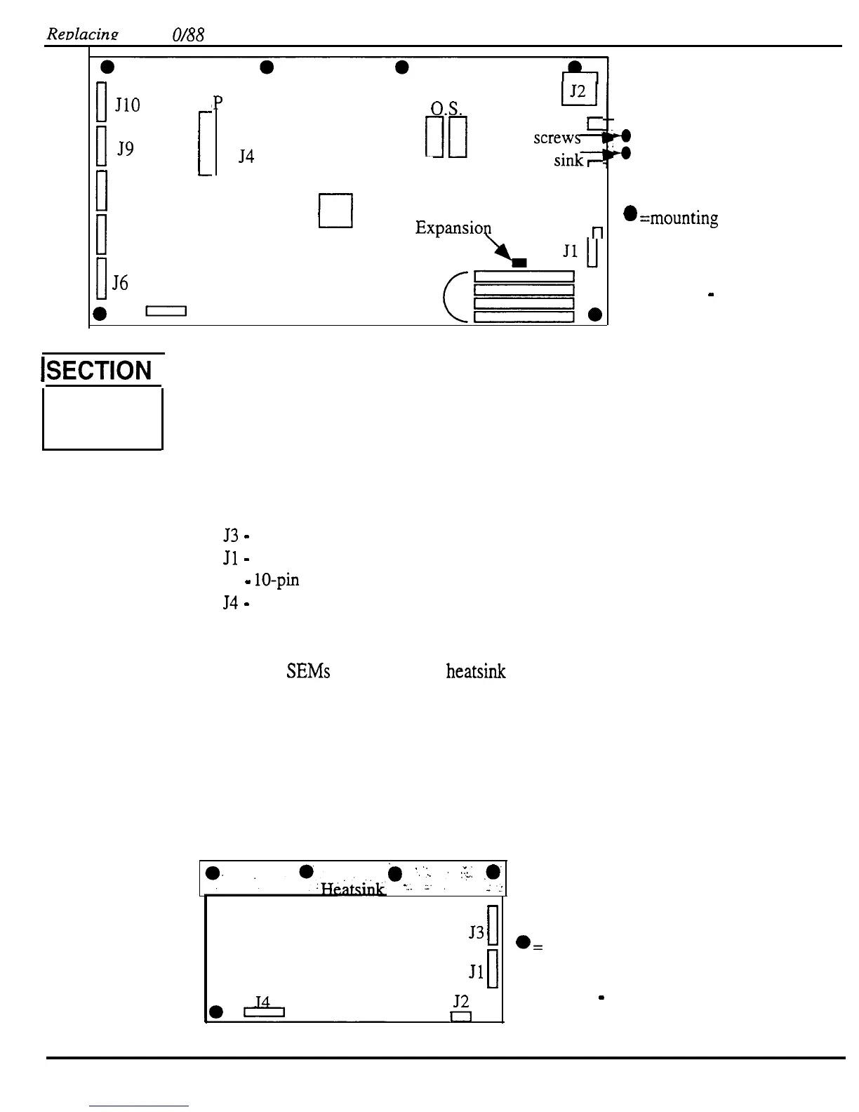
O/88
Modules
0
JlO
1
ES
[
‘P
Ill
54
L-l
J2
O.S.
c
two
screw-
into heat
sink7
0
J9
J8
0
J7
0
56
J5
OTTO
El
Expansioq Jumper
t-t
Four SIMM
sockets
ISECTION
I
B
Removing 1.
2.
3.
4.
Irlstalling 5.
6.
7.
8.
9.
Replacing the Analog Board
:
1
a
=mounting screw
location
Figure 17
-
ASR- 10 Digital Board
Remove all cables connected to the ASR-10, including the power cord.
Turn the unit upside-down and remove all the screws from the base and rear panel.
Remove all cables connected to the analog board.
a)
53
-
6-pin cable to the power supply board.
b)
Jl
-
34-pin ribbon cable to the digital board,
c)
J2
-
lo-pin ribbon cable to the analog jack board, and
d)
54
-
20-pin ribbon cable to the analog jack board.
Remove the six (6) screws (ASR-88 has 4 screws and 2 stand offs) from the analog
board:
a)
Four (4) SEMs from the analog heatsink to keyboard bracket,
b) One (1) from center support bracket, and
c)
One (1) from the analog bracket.
Install the six (6) screws (see 4 a-c).
Connect all the cables (see 3 a-d).
Place the bottom panel in place.
Power up, test the unit.
Install all the screws into the bottom panel.
.
-...
;,
,’
CL:
.F;
i
‘,”
53
0
II
.=
mounting screw
Jl
location
::
l
Figure 18
-
ASR- 10 Analog Board
42
ASR Service Manual

 Loading...


