Replacing ASR-I
O/88
Modules
Remove any cable clips Mylar Insulator between disk
beneath e
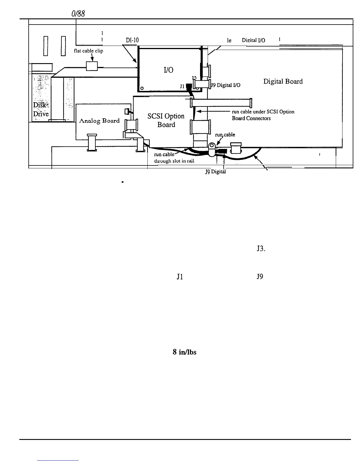
DI-10
Board drive ca
Ie
and Didtal
I/O
Board
/
/
0
0
/
DI-10
-
Digital I/O Board
ve
through rounded cable clamp
J9
Digitrh
I/O
\
Analog Main Board Power Cable
Analog Jack Board
Digital Jack Board
I
I
\
Figure 23
-
Installing a DI-10 Board into an ASR-10 Keyboard Unit
NOTE:
If you accidentally put the board on in the wrong way, it may be removed by pushing in the
center tab of each plastic standoff. Do each comer one at a time, lifting the board just high
enough to keep the plastic tab from relocking. When all four are done, the board can be lifted
off and reseated in the proper direction.
6.
Connect one end of the 20-pin ribbon to the DI-10 board at
53.
7.
Feed the dual shielded cable through the slot in the metal work under the back (toward
you) of the SCSI board mounting area.
8.
Plug the dual shielded cable into
Jl
of the DI-10 board and
J9
of the digital jack board.
Note that the connectors are keyed.
9.
Remove the mounting screw from the lower left hand comer of the digital board. This
screw also holds in place a rounded cable clamp with a multi-conductor power cable
going through it. Place the dual shielded cable into the cable clamp with the power cable.
Reattach the cable clamp and digital board to the frame as it originally was.
10. Make sure that the unit is working properly.
11. Turn the unit off and turn it upside down and replace all the screws on the bottom plate
and rear panel (use no more than
8
idlbs
of torque).
52
ASR Service Manual

 Loading...


