Installing the S4 Chassis
Enterasys S-Series S4 Chassis Hardware Installation Guide 3-11
6. Place the bundled cables in the cable management clip.
7. Close the cable management clip.
Chassis Bonding and Grounding
Installing the chassis as described in this chapter meets the protective earth grounding
requirements of the National Electrical Code (NEC) UL 60950 and IEC 60950 standards. However,
in some cases it is necessary to use an alternative grounding method at installation sites that must
meet the Telcordia GR-1089 Section 9, Bonding and Grounding Requirements, or national
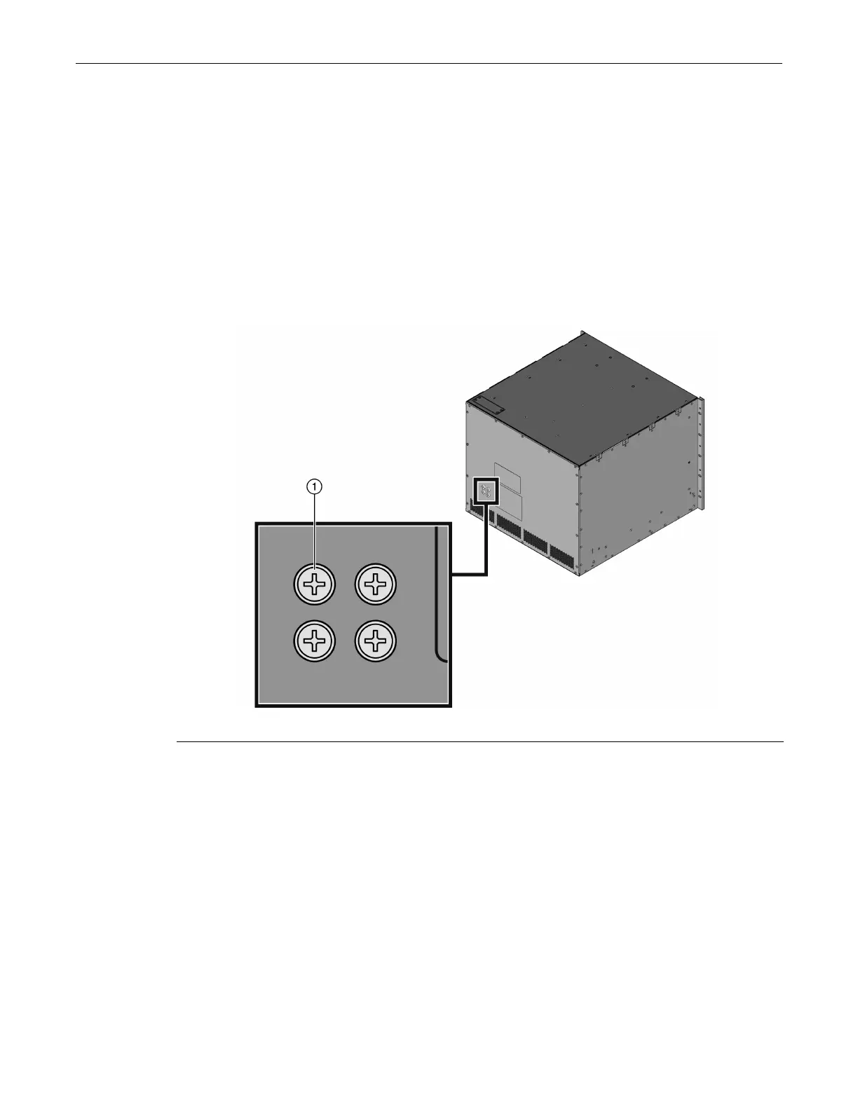
deviations. To meet these requirements, use the four tapped holes located on the rear of the
chassis.These holes meet the hole grounding bolt pattern requirements, as shown in Figure 3-10.
Figure 3-10 Telcordia GR-1089 Grounding Hole Pattern
To ground the chassis according to the Telcordia GR-1089 Section 9, Bonding and Grounding
Requirements, or when using the S-DC-PS power supplies, a connection is needed between the
chassis and the enclosure metalwork or a nearby point on the Central Office (CO) Ground system
or earth ground. To fabricate and install a grounding wire, proceed as follows:
1. Cut an 8 AWG (6
2
mm) stranded-copper wire to length, long enough to reach from the
grounding location of the chassis to the selected grounding location on the CO Ground, earth
ground, or enclosure metalwork.
2. Install a listed two-hole compression-type connector on both ends of the grounding wire.
3. Apply a suitable antioxidant to the chassis grounding location and unpainted surface
grounding location on the CO Ground or enclosure metalwork.
4. Connect one ground cable two-hole connector to the chassis using two of the 1/4-20 screws
shipped with the chassis. Connect the two-hole connector at the other end of the cable to the
CO Ground or enclosure metalwork using user-supplied screws.
1 Ground screws