Connecting to the COM Port for Local Management
Enterasys S-Series S4 Chassis Hardware Installation Guide 3-33
Adapter Wiring and Signal Assignments
Table 3-9 shows the COM port adapter wiring and signal diagram. Table 3-10 shows the VT series
port adapter wiring and signal diagram.
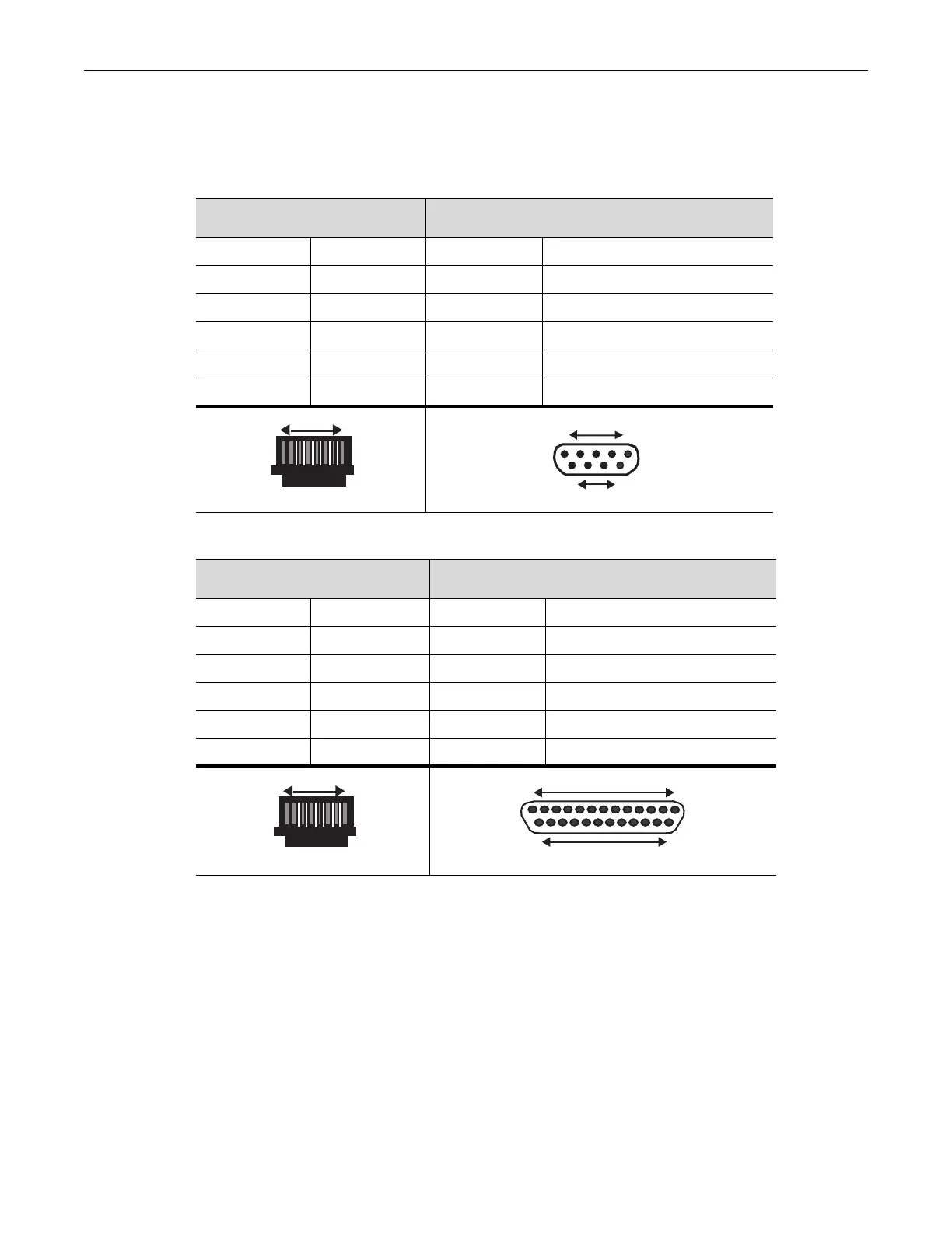
Table 3-9 COM Port Adapter Wiring
RJ45 DB9
Pin Conductor Pin Signal
1 Blue 2 Receive (RX)
4 Red 3 Transmit (TX)
5 Green 5 Ground (GRD)
2 Orange 7 Request to Send (RTS)
6 Yellow 8 Clear to Send (CTS)
Table 3-10 VT Series Port Adapter Wiring
RJ45 DB25
Pin Conductor Pin Signal
4 Red 2 Transmit (TX)
1 Blue 3 Receive (RX)
6 Yellow 5 Clear to Send (CTS)
5 Green 7 Ground (GRD)
2 Orange 20 Data Terminal Ready
RJ45 Connector (Female)
Pins
81
69
DB9 Connector (Female)
15
Pins
RJ45 Connector (Female)
Pins
81
DB25 Connector (Female)
Pins
25
14
13 1