Installing and Removing an S-DC-PS Power Supply
3-20 Chassis Setup
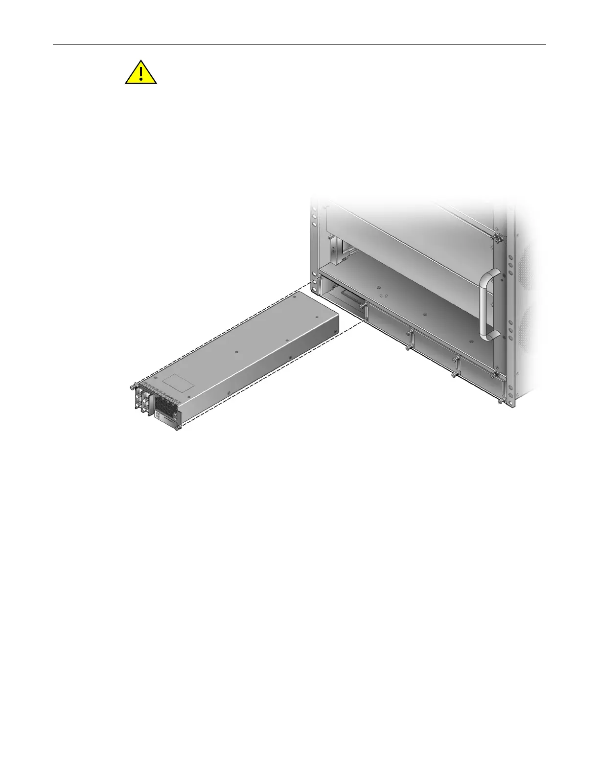
6. Insert the power supply into the opening and carefully slide the module until it connects to
the backplane, as shown in Figure 3-14. The module should be nearly flush with the face of the
S4 chassis. If significant resistance is encountered before the power supply is seated, remove
and reinsert it. Do not force the module into place.
Figure 3-14 Installing the S-DC-PS Power Supply
7. Secure the power supply to the chassis by tightening the captive screw.
8. If you are installing additional power supplies, remove the coverplates
from their slots by
loosening their captive screws and repeat steps 4 through 8 to insert them into the chassis.
Keep the coverplates in a safe location in the event you need to remove the power supply and
replace the coverplate.
9. Connect the chassis to earth ground using the earth ground connection on the back of the unit.
a. Cut an 8 AWG (6
2
mm) stranded copper wire to a length suitable for connecting the
grounding location of the chassis to the building earth ground.
b. Install a listed 2-hole, compression-type connector on both ends of the grounding wire.
c. Apply a suitable antioxidant to the chassis grounding location and the unpainted surface
building earth ground.
d. Connect the 2-hole connector at one end of the ground cable to the chassis using two of
the 1/4-20 screws shipped with the chassis. Connect the 2-hole connector at the other end
of the cable to the building earth ground using user-supplied screws.
e. Torque the screws to 67 in-lb. (± 5%).
Caution: Forcing a misaligned power supply into place can damage the power supply or chassis
backplane.
Precaución: Colocar de manera forzada una fuente de poder o no colocarla bien alineada podría
dañarla y/o maltratar el panel posterior del chasis.