Connecting to the COM Port for Local Management
Enterasys S-Series S4 Chassis Hardware Installation Guide 3-31
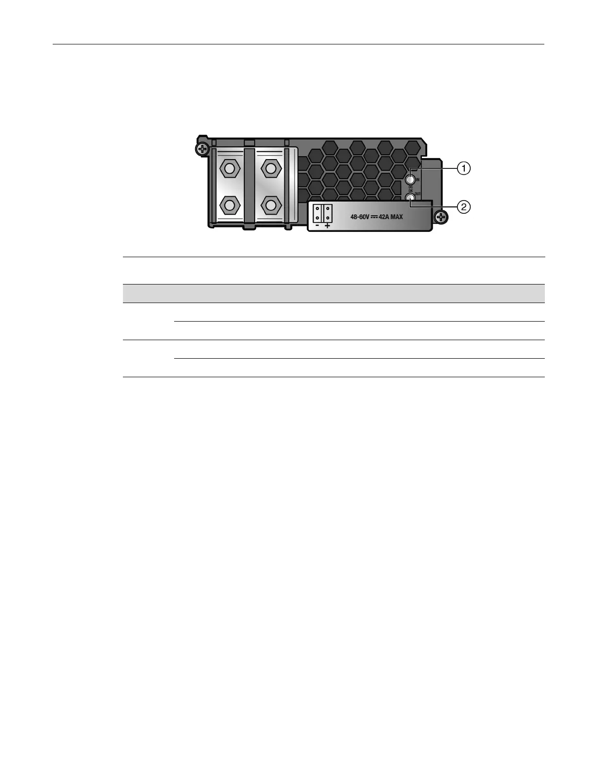
S-DC-PS Power Supply LEDs
Refer to Figure 3-19 for the location of the S-DC-PS power supply LEDs. Table 3-5 describes the
states of the power supply LEDs.
Figure 3-22 S-DC-PS Power Supply LEDs
Connecting to the COM Port for Local Management
This section describes how to install a UTP cable with RJ45 connectors and optional adapters to
connect a PC or VT series terminal to an Enterasys Networks device to access Local Management.
This section also details adapter pinout assignments.
What Is Needed
The following is a list of the parts that may be needed depending on the connection:
• RJ45-to-DB9 female adapter (supplied with the S4 chassis)
• UTP cable with RJ45 connectors (supplied with the S4 chassis)
• RJ45-to-DB25 female adapter (customer-supplied)
Using the UTP cable with RJ45 connectors and the RJ45-to-DB9 adapter, you can connect an S4
chassis RJ45 COM port to a PC running a VT series emulation software package.
Using the UTP cable and an optional RJ45-to-DB25 female adapter, you can connect an S4 chassis
RJ45 COM port to a VT series terminal or VT type terminals running emulation programs for the
VT series.
1 DC OK IN LED 2 DC OK OUT LED
Table 3-8 S-DC-PS Power Supply LED Status Definitions
LED LED Color Status
DC OK IN Green Sufficient DC power supply (influx)
Off Power supply malfunctioning or unplugged
DC OK
OUT
Green Power supply successfully providing 12 VDC to the system
Off Power supply malfunctioning or unplugged