5050 CONTROL UNIT
Technical Manual & Cabling Instructions
19.10.2012
Epec Oy reserves all rights for improvements without prior notice
Epec Oy Postiosoite/Postal address Puhelin/Phone Fax Internet
Tiedekatu 6 PL/P.O.Box 194 +358-(0)20-7608 111 +358-(0)20-7608 110 www.epec.fi
FIN-60320 Seinäjoki FIN-60101 Seinäjoki, Finland
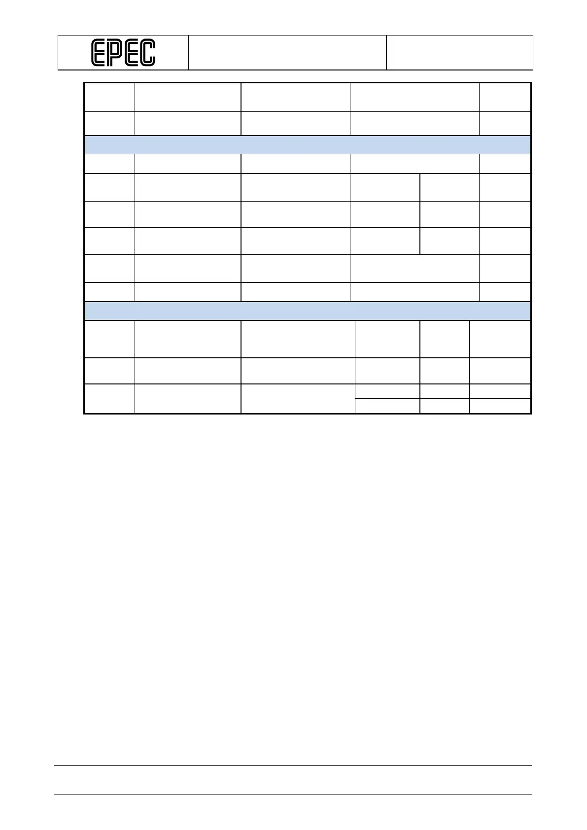
Duty
PWM
PWM
Duty cycle
(Note 2, 9)
0 to 100 %
Res
PWM
PWM Resolution (Note 3) 0,1 %
Digital status input
R
I
Input Resistance
Output Off
Typ. 12 kΩ
V
IH
Digital status input
High Voltage level
Output Off (Note 5)
3,2 V
V
IL
Digital status input
Output Off
1,9 V
V
I-range
Input voltage range (Note 12) -0,5
VDCPOWER2
+ 0,2V
V
t
I
Digital Status Input
Pulse Width
(Note 2, 4, 11)
tC + 25% ms
C
I
Input pin capacitance
typ. 1
nF
Output/input voltage monitoring
V
0-range
Nominal Output/input
Voltage measuring
range
(Note 10) 0 55 V
V
I-prop
Measuring accuracy
Calculated
+/-1 %
V
I-zero
Offset Error Calculated
Note 1: Frequency of a (PWM) Pulse Width Modulation is = 1 / Period
Note 2: The duty cycle is defined as the percentage of digital ‘high’ to digital ‘low’ signals present
during a PWM period.
Note 3: The PWM resolution is defined as the maximum number of pulses that you can pack into a
PWM period.
Note 4: tC denotes software cycle time.
Note 5: Exceeding the max value might cause damage to input.
Note 6: The maximum output current depends on the load, PWM frequency and temperature.
Note 7: The firmware limits the maximum current to 2,5 A. When the current exceeds the value more
than 200 ms, the output is switched off. The current can be adjusted to be less than 2,5 A by software.
Note 8: When both outputs in a same package are used the total power output can be up to 4A. For
example if output1 continuous load is 2,5A then continuous max load for output2 is 4A – 2,5A = 1,5A.
Note 9: When the frequency increases, the actual duty cycle may be bigger than the value that has
been set.
Note 10: The output must be kept in off state when used as an input. The measured voltage must not
exceed the input voltage.
Note 11: Pulse width must be greater that the software cycle time. For example with 50/50 pulse ratio,
the pulse frequency is 1 / (2*pulse width)
Note 12: Overload conditions