5050 CONTROL UNIT
Technical Manual & Cabling Instructions
19.10.2012
Epec Oy reserves all rights for improvements without prior notice
Epec Oy Postiosoite/Postal address Puhelin/Phone Fax Internet
Tiedekatu 6 PL/P.O.Box 194 +358-(0)20-7608 111 +358-(0)20-7608 110 www.epec.fi
FIN-60320 Seinäjoki FIN-60101 Seinäjoki, Finland
8.3 Plugging and unplugging the cables/connectors
All Epec control units use heavy duty gold plated, locked and sealed AMPSEAL connectors.
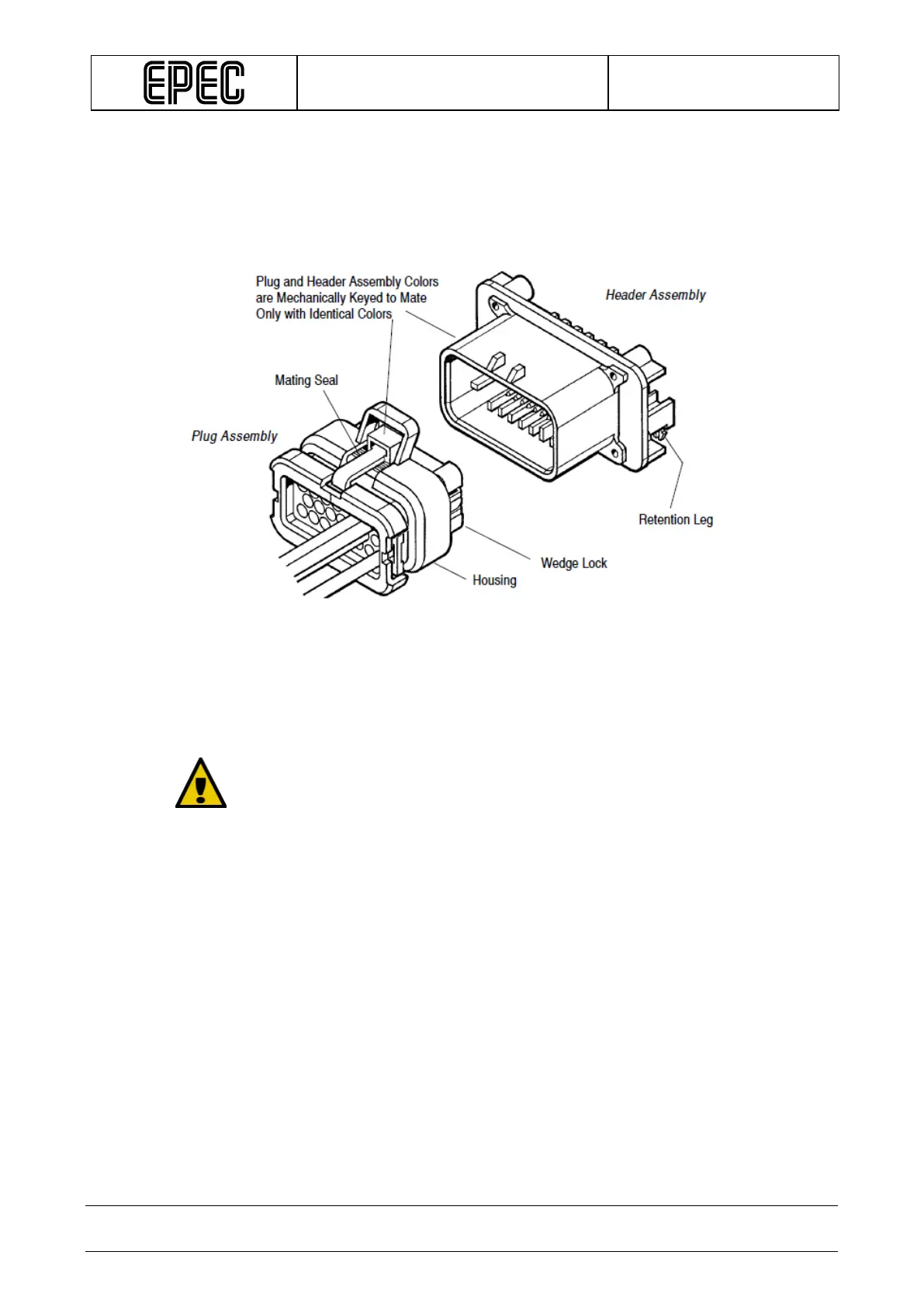
The following figure shows an example of AMP23 connector:
• Gold plated AMPSEAL connectors pack a current of 15 amperes per contact and
tolerate operating temperature range.
• All module connectors are mechanically keyed to mate only with identical colours (blue,
grey and black).
When connecting, make sure that:
• connectors are pressed down to the bottom and that they are locked
• the connectors are clean (avoid moisture or dirt inside the connector)
• unused connectors are covered with empty connectors of the same colour
(this helps to keep the control unit connectors dry and protected)
• all cables, connectors and tools are of correct type, and sufficiently high
quality, and suitable for this kind of use (protection for moisture, mechanical
stability, power durability, coupling resistance among other things)
• there is a sufficient margin (slack) left in the cables to prevent the torsion of
the connectors
•
wires are bound to control unit cover base knob with cable ties
The following figure describes some general instructions about the connectors.