5050 CONTROL UNIT
Technical Manual & Cabling Instructions
19.10.2012
Epec Oy reserves all rights for improvements without prior notice
Epec Oy Postiosoite/Postal address Puhelin/Phone Fax Internet
Tiedekatu 6 PL/P.O.Box 194 +358-(0)20-7608 111 +358-(0)20-7608 110 www.epec.fi
FIN-60320 Seinäjoki FIN-60101 Seinäjoki, Finland
4.3.3 DI/PI_Type003
• This type of pin is a ground referenced input (DI) including a pulse counting (PI) feature.
• Pulse inputs can be used as a 1 or 2 channel pulse counter and they have a possibility for
reset pulse. Possible software channels and pairs are listed in section
SW channels for
Pulse Inputs.
• The configurable features are controlled by a control signal:
• pull-up enable selection
• When the pull-up to internal +10V is enabled, it controls two input pins as one. The pairs
are indicated with lower case characters in the pin table's Group column in section
Pinout
Map.
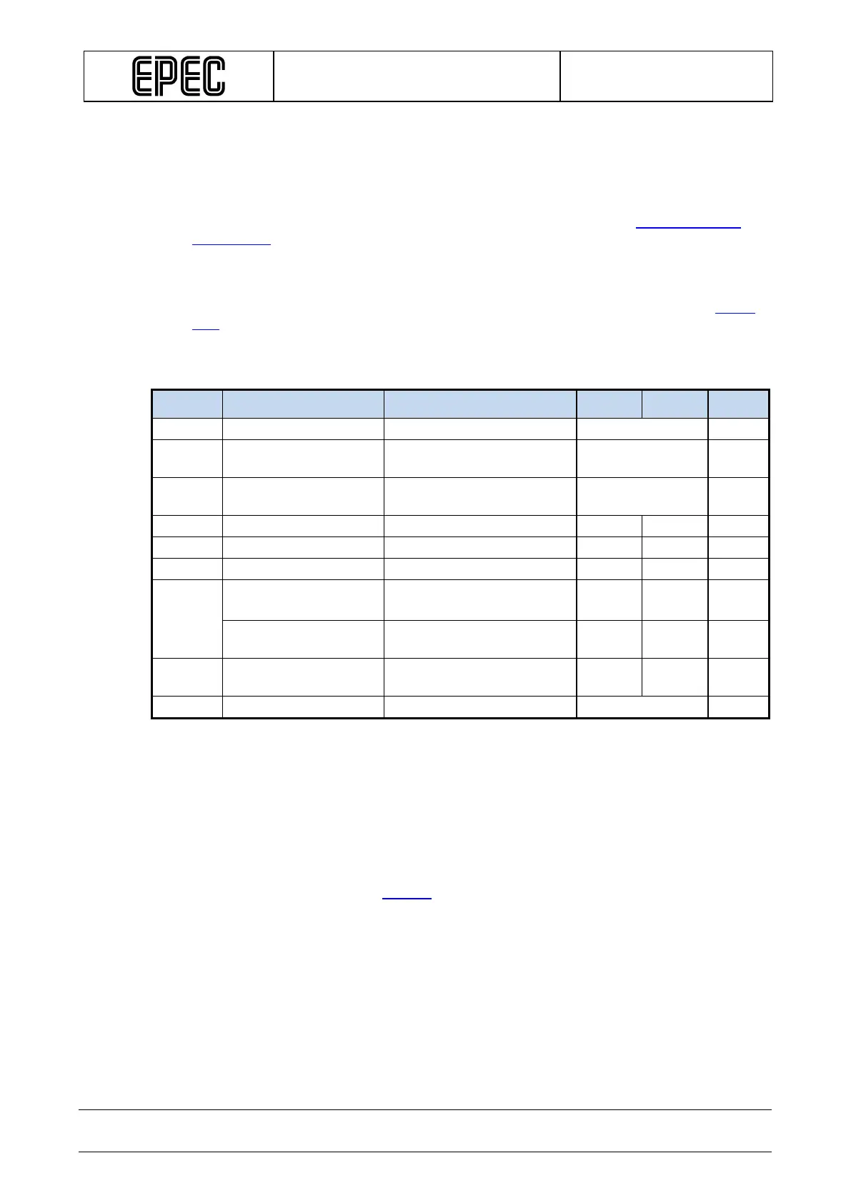
Electrical characteristics
Symbol Parameter Conditions Min Max Units
Referenced to GND (Note 1)
R
PU
Pull-up Resistance
Referenced to +10V (Note
typ. 2,2 kΩ
V
Level
Output voltage
Unconnected pin, +10_PU
typ. 8,3 V
f
I
Input Frequency
(normal digital input)
tC= 4ms (Note 4,5,9)
250 Hz
Input Frequency
(Note 7,8,10) 5 20000 Hz
t
I
Input Pulse Width
(Note 7) 0,025 250 ms
Note 1: A pull-up resistor is not selected.
Note 2:When pull-up resistor is selected.
Note 3: Exceeding the max values might cause damage to input.
Note 4: These parameters depend on software cycle time.
Note 5: Applies to inputs used as normal digital input. Violating this rating may lead to application
program not noticing all input state transitions.
Note 6: Overload conditions
Note 7: Violating this rating may lead to system not recognizing all input state transitions.
Note 8: It is possible to configure a smaller minimum frequency for some of the pins, see I/O
table (Information column) in section
I/O List.
Note 9: tC denotes software cycle time.
Note10: Max value can be reached by 2-98% pulse ration.