5050 CONTROL UNIT
Technical Manual & Cabling Instructions
19.10.2012
Epec Oy reserves all rights for improvements without prior notice
Epec Oy Postiosoite/Postal address Puhelin/Phone Fax Internet
Tiedekatu 6 PL/P.O.Box 194 +358-(0)20-7608 111 +358-(0)20-7608 110 www.epec.fi
FIN-60320 Seinäjoki FIN-60101 Seinäjoki, Finland
4.3 Digital Input / Pulse Input
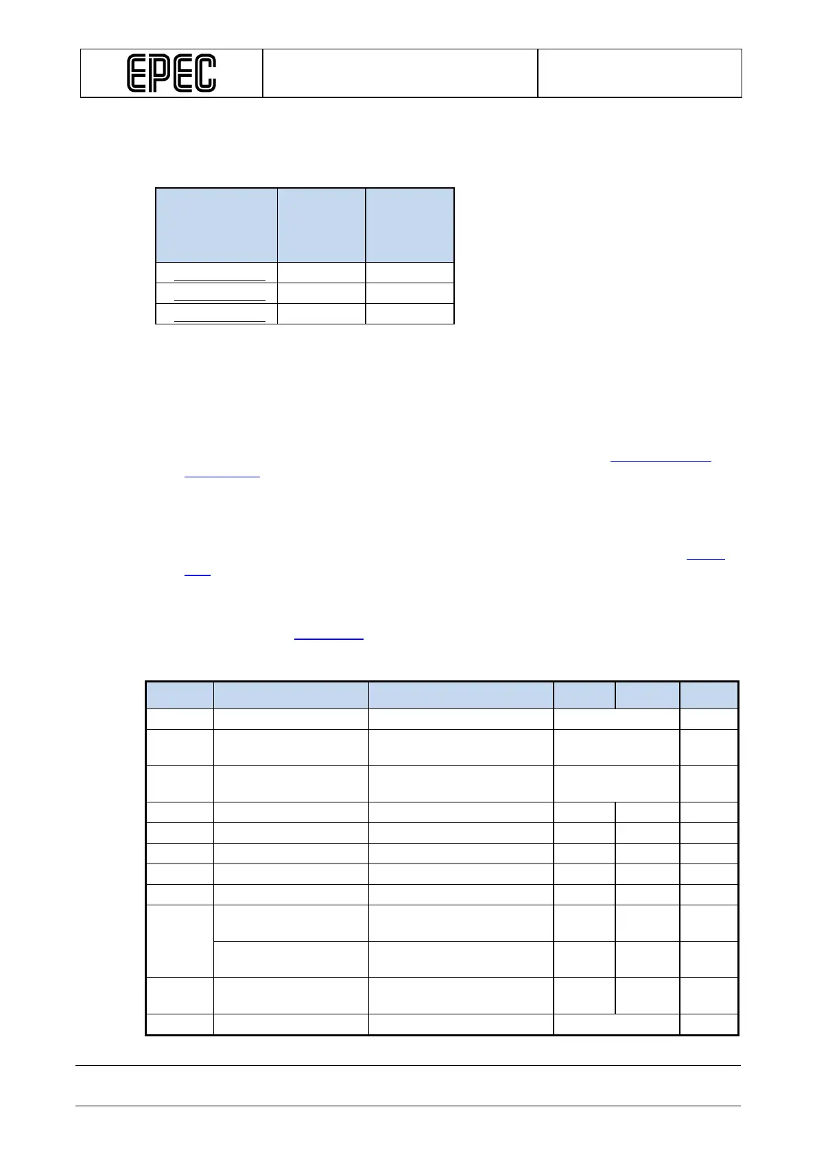
This product has three different types of DI/PI pins. The following table shows their differences:
Pin type
Pull-up
selection
Input
voltage
range
selection
4.3.1 DI/PI_Type001
• This type of pin is a ground referenced input (DI) including a pulse counting (PI) feature.
• Pulse inputs can be used as a 1 or 2 channel pulse counter and they have a possibility for
reset pulse. Possible software channels and pairs are listed in section
SW channels for
Pulse Inputs.
• The configurable features are controlled by two control signals:
• pull-up enable selection
• input voltage range selection
• When the pull-up to internal +10V is enabled, it controls two input pins as one. The pairs
are indicated with lower case characters in the pin table's Group column in section
Pinout
Map.
• The input voltage range selection controls two input pins as one. This local signal defines
threshold voltage levels for both inputs. This feature provides more flexibility to sensor
connections. The pairs are indicated with lower case characters in the pin table's Group
column in section
Pinout Map.
Electrical characteristics
Symbol Parameter Conditions Min Max Units
Referenced to GND (Note 1)
R
PU
Pull-up Resistance
Referenced to +10V
typ. 2,2
kΩ
V
Level
Output voltage
Unconnected pin, +10V_PU
typ. 8,3 V
f
I
Input Frequency
tC = 4 ms (Note 4, 5, 8, 9) 250 Hz
Input Frequency
(Note 7, 10) 5 20000 Hz
t
I
Input Pulse Width
(Note 7) 0,025 250 ms