5050 CONTROL UNIT
Technical Manual & Cabling Instructions
19.10.2012
Epec Oy reserves all rights for improvements without prior notice
Epec Oy Postiosoite/Postal address Puhelin/Phone Fax Internet
Tiedekatu 6 PL/P.O.Box 194 +358-(0)20-7608 111 +358-(0)20-7608 110 www.epec.fi
FIN-60320 Seinäjoki FIN-60101 Seinäjoki, Finland
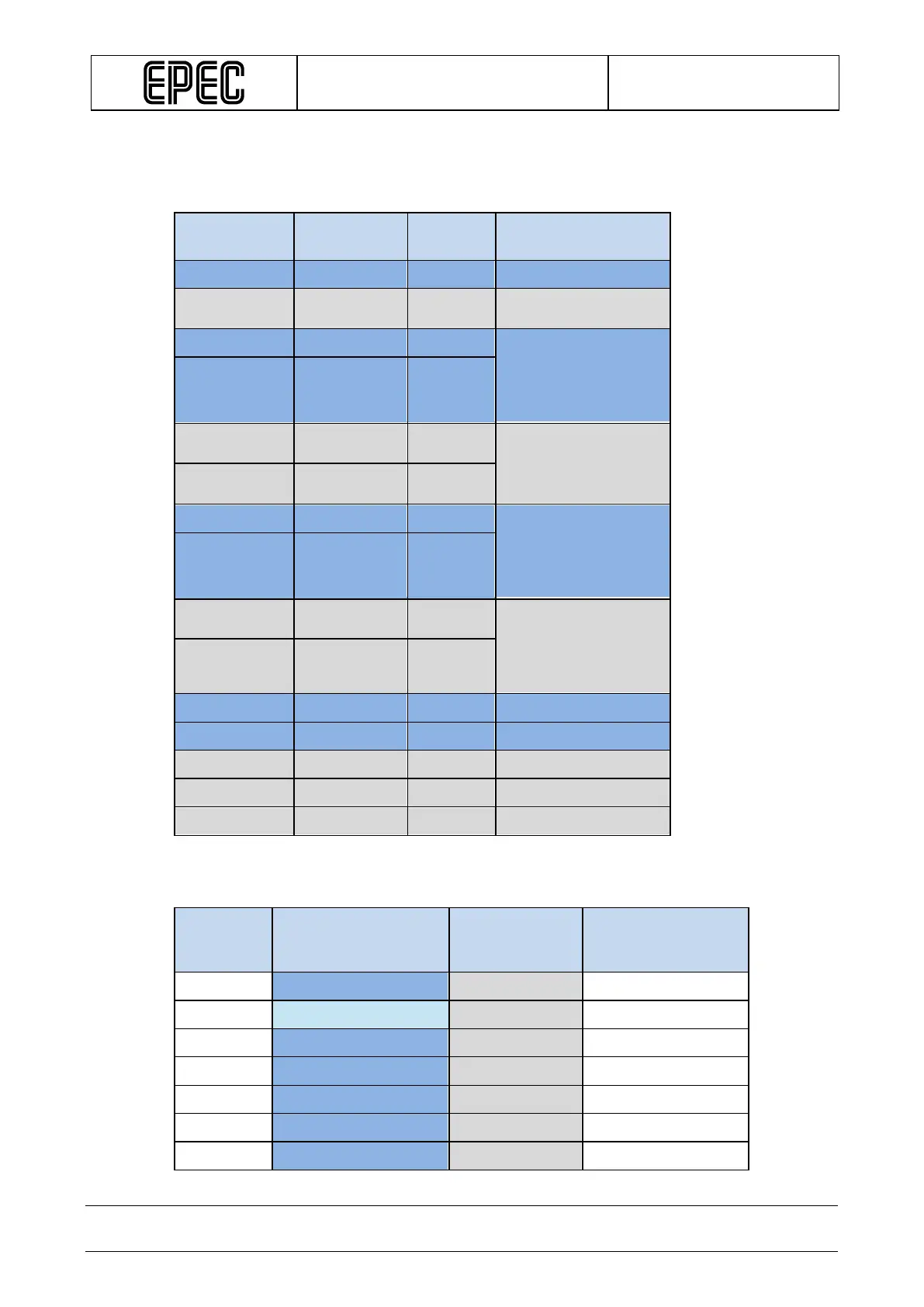
4.8 Power supply pins and limitations
Power supply pins are located in the following pins:
Connector
pin number
Pin Name
Current /
Pin
Note
X1.1
LOGIC GND
X1.24
Power
X2.1
Power1 GND 10 A The maximum sum of
GND pin currents
should not
continuously exceed
X2.2
Power1 GND 10 A
X2.24
Power
10 A
The maximum sum of
supply pin currents
cannot exceed 14 A.
X2.25
Power
10 A
X3.1
Power2 GND 10 A The maximum sum of
GND pin currents
should not
continuously exceed
X3.2
Power2 GND 10 A
X3.24
Power
10 A
The maximum sum of
supply pin currents
should not
continuously exceed
X3.25
Power
Supply2
10 A
X2.5
+5 V REF
X3.20
+5 V REF
X1.8
+10 V REF
X2.4
+10 V REF
X3.13
+10 V REF
The following table describes which power gives certain pins the currency needed:
Connector
pin
number
Pin Type Powered by
Current/
voltage
X1.12 PWM/DO/DI/CM
Power 1 2A
X1.22 PWM/DO/DI
Power 1 4A
X1.23 PWM/DO/DI/CM
Power 1 2A
X1.29 PWM/DO/DI
Power 1 2A
X1.30 PWM/DO/DI
Power 1 2A
X1.31 PWM/DO/DI
Power 1 2A
X1.32 PWM/DO/DI
Power 1 2A