5050 CONTROL UNIT
Technical Manual & Cabling Instructions
19.10.2012
Epec Oy reserves all rights for improvements without prior notice
Epec Oy Postiosoite/Postal address Puhelin/Phone Fax Internet
Tiedekatu 6 PL/P.O.Box 194 +358-(0)20-7608 111 +358-(0)20-7608 110 www.epec.fi
FIN-60320 Seinäjoki FIN-60101 Seinäjoki, Finland
4.4 Analog Input / Digital Input
4.4.1 AI/DI_Type011
• This type of pin is an analog input and a digital input
• The configurable features are controlled by two control signals:
• One control signal is for selecting:
• Voltage mode: High impedance input for signal from 0 to 10V with or without
pull-up.
• Current mode: Low impedance input for signal from 0 to 22mA.
• One control signal is for selecting (when in voltage mode):
• Pull-up mode to +10V by a resistor
• Pull-up mode to GND by a resistor
Configure the pin to current mode before applying the current signal.
When measuring current (mA), the sensor connected to 5050 unit’s AI/DI pin
must not be powered up before the 5050 control unit is operational. Otherwise
the sensor’s input signal is not received correctly.
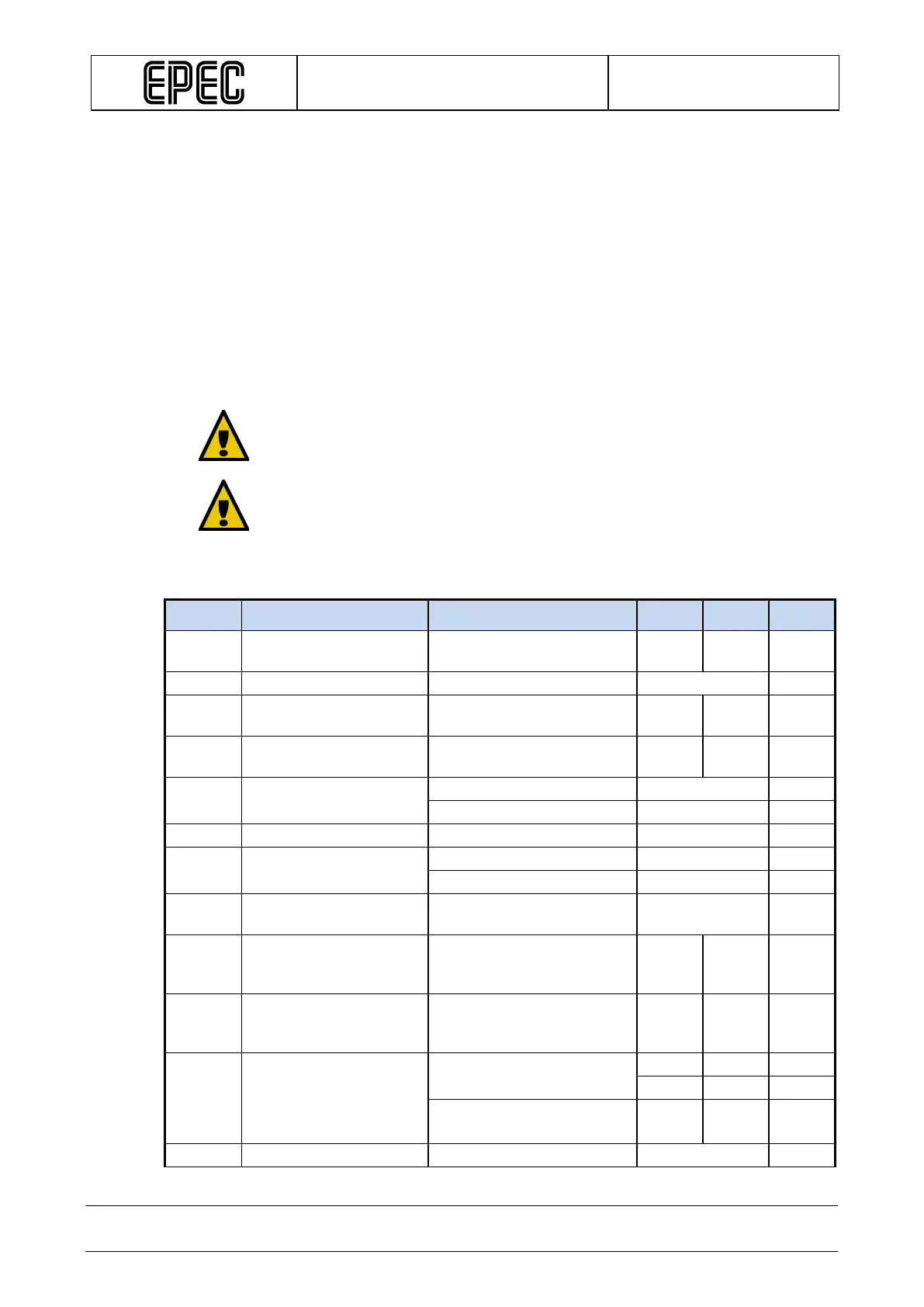
Electrical characteristics
Symbol Parameter Conditions Min Max Units
V
I
Input Voltage measuring
Voltage mode 0,0 10,0 V
V
I-PU
Pull-up Voltage
Voltage mode 0,0 10,0 V
I
I
Input Current measuring
Current mode 0,0 22,7 mA
R
I
Input Resistance
t
I
Time Constant of Input
Low Pass Filter
t
I-pull-up
Time Constant of Pull-up
Pull-up voltage measuring
typ. 0,78 ms
V
I-prop
Input Measuring
accuracy Proportional
Calculated +/-1 %
V
I-prop-PU
Pull-up Voltage
Measuring accuracy
Calculated
+/-1 %
V
I-zero
Offset Error
Voltage mode
Calculated
Current mode
+/-
0,022
mA