5050 CONTROL UNIT
Technical Manual & Cabling Instructions
19.10.2012
Epec Oy reserves all rights for improvements without prior notice
Epec Oy Postiosoite/Postal address Puhelin/Phone Fax Internet
Tiedekatu 6 PL/P.O.Box 194 +358-(0)20-7608 111 +358-(0)20-7608 110 www.epec.fi
FIN-60320 Seinäjoki FIN-60101 Seinäjoki, Finland
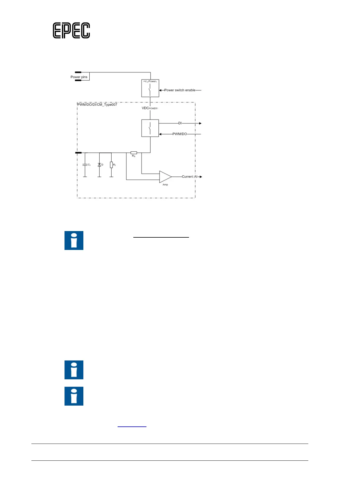
Functional block diagram
Other Information
Refer to section Connection Examples to see examples on how to connect some
external actuators or sensors when using this type of pin.
4.2.4 PWM/DO/DI/CM_Type008
Output (PWM/DO)
• This type of pin is a current sourcing output with a current and voltage measurement
features (the pin connects the load to a positive supply voltage through the shunt resistors).
• These outputs have a switching element called a smart FET. It has integrated features to
protect itself but also the external pin, wiring and actuator.
• These outputs are capable to generate pulse width modulated (PWM) output signals.
• When used as an output, the input feature indicates the output FET's state
Before the supply voltage can be connected to an output pin, the related power
switch must be switched on as well.
The FET outputs are grouped into pairs:
• The maximum continuous current for single output in the pair is 2,5 A.
• The maximum continuous current for the pair is 4 A.
The pairs are indicated with upper case characters in the pin table's Group column