5050 CONTROL UNIT
Technical Manual & Cabling Instructions
19.10.2012
Epec Oy reserves all rights for improvements without prior notice
Epec Oy Postiosoite/Postal address Puhelin/Phone Fax Internet
Tiedekatu 6 PL/P.O.Box 194 +358-(0)20-7608 111 +358-(0)20-7608 110 www.epec.fi
FIN-60320 Seinäjoki FIN-60101 Seinäjoki, Finland
5 BUS CONNECTIONS
5.1 CAN bus
CAN interface
• Codesys 2.3 IDE communication is supported for CAN1.
• Higher layer protocol is user programmable (CAN1, CAN2, CAN3, CAN4)
communication
• The physical interface of CAN is according to ISO 11898 and CAN 2.0B protocol
• Download of the PLCopen application can be done via CAN1.
• All interfaces support bit rates 10, 20, 50, 125, 250, 500, 800, 1000 kbit/s
• All interfaces can be configured as listen only mode. Exception is CAN1 which is in boot
up normal mode because it is used for Codesys communication.
• 11-bit and 29-bit message receive and transmit are supported.
• Transmitting of remote frames is supported for all CAN interfaces.
• Support for receiving one remote frame is supported. This is received for control unit's
own node guard functionality.
CAN bus connection pins
This product contains 4 CANs for the CAN bus connection. CAN1 has duplicated pins, so it can
be easily used for chaining the control units.
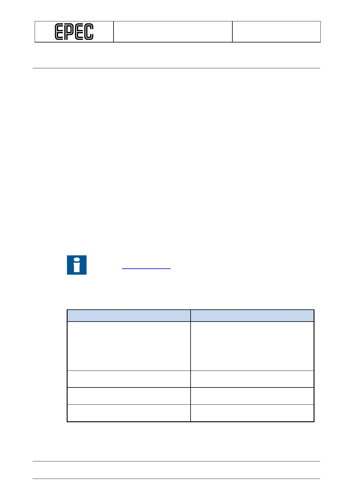
In CAN1, it is possible to connect the internal termination resistor. For more information refer
to section System topologies.
The CAN communication pins are located in the control unit's connector 1 (grey AMP35) as
follows:
Designation Pin number
CAN1 interface, system interface
user programmable communication
X1.5 (CAN1 H)
X1.6 (CAN1 H)
X1.7 (CAN1 H terminator)
X1.17 (CAN1 L)
X1.18 (CAN1 L)
X1.19 (CAN1 L terminator)
CAN2 interface, user programmable
communication
X1.4 (CAN2 H)
CAN3 interface, user programmable
communication
X1.3 (CAN3 H)
CAN4 interface, user programmable
communication
X1.2 (CAN4 H)