5050 CONTROL UNIT
Technical Manual & Cabling Instructions
19.10.2012
Epec Oy reserves all rights for improvements without prior notice
Epec Oy Postiosoite/Postal address Puhelin/Phone Fax Internet
Tiedekatu 6 PL/P.O.Box 194 +358-(0)20-7608 111 +358-(0)20-7608 110 www.epec.fi
FIN-60320 Seinäjoki FIN-60101 Seinäjoki, Finland
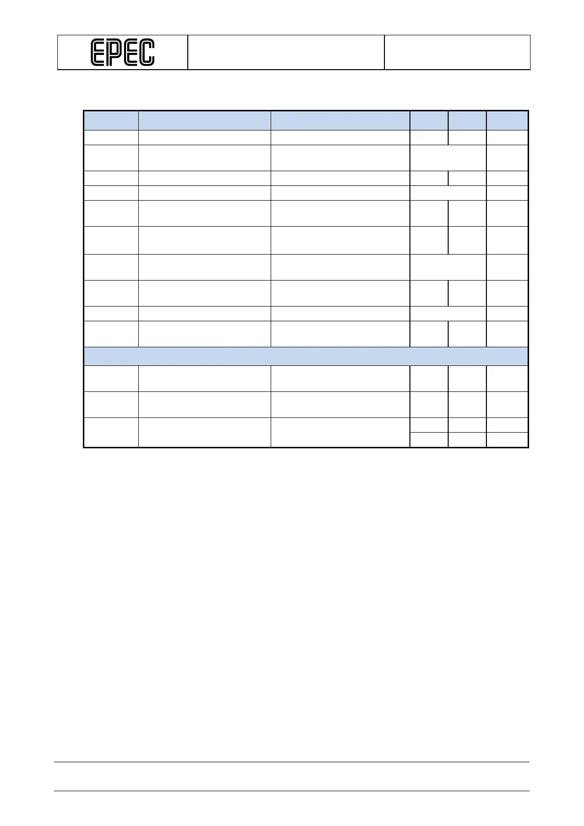
Electrical characteristics
Symbol Parameter Conditions Min Max Units
P
Logic
Logic Power Consumption
No external loads,
typ. 2,2 W
Max through current per pin
V
I-Load-dump
Max Input transient Voltage
(Note 1) 97,5 V
V
I-max
Max Continuous Input
Voltage level
Each power group
-58 60 V
V
OVP-Reg
Regulated Overvoltage
typ. 43 V
V
OVP-oper.
Operational Overvoltage
(Note 3,4) 50 V
Undervoltage threshold level
V
RVP
Reverse Voltage Protection
No extra facilities needed
-58 V
Voltage monitoring
V
I-range
Nominal Input Voltage
0 55 V
V
I-prop
Measuring accuracy
Calculated
+/-1 %
V
I-zero
Offset Error Calculated
Note 1: Load dump protection according to ISO7636-2: 2004 pulse 5, Us=+70V
Note 2: Limited functionality when the voltage is higher than the nominal. If the voltage is less than 8,3
V, the control unit is in non-operational state.
Note 3: This parameter is only related to the logic power input.
Note 4: This parameter is influenced by +10V REF’s load level.
Note 5: Nominal voltage level where reverse protection will be activated. Keep in mind the fuse
parameters, such as the reaction time.