5050 CONTROL UNIT
Technical Manual & Cabling Instructions
19.10.2012
Epec Oy reserves all rights for improvements without prior notice
Epec Oy Postiosoite/Postal address Puhelin/Phone Fax Internet
Tiedekatu 6 PL/P.O.Box 194 +358-(0)20-7608 111 +358-(0)20-7608 110 www.epec.fi
FIN-60320 Seinäjoki FIN-60101 Seinäjoki, Finland
8.4.2 CAN bus
The CAN bus cable is the neural backbone of the whole system and should be
designed and constructed with extra care.
• In all Epec 5050 control units, the bus connections can be found in grey AMP 35 pin
connector (connector1).
• 5050 contol unit's CAN1 is equipped with double pins that enables cabling without
branching the wire harness
Cable
• It is recommended to use high quality and twisted (approx. 1 round/ 1 inch) CAN bus cable.
• Normal UTP (Unshielded Twisted Pairs) cable is well suited for distances under
approximately 10 meters.
• In longer distances, and especially if there is possibility for electromagnetic interference, it
is highly recommended to use shielded and twisted cable for CAN bus, also for shorter
distances.
• To avoid electromagnetic interference (EMI), locate the bus cable as far away from high-
current carrying cables as possible. Generally the amount of the connections and
connectors should be minimized to maximize security; also all connections should be done
carefully.
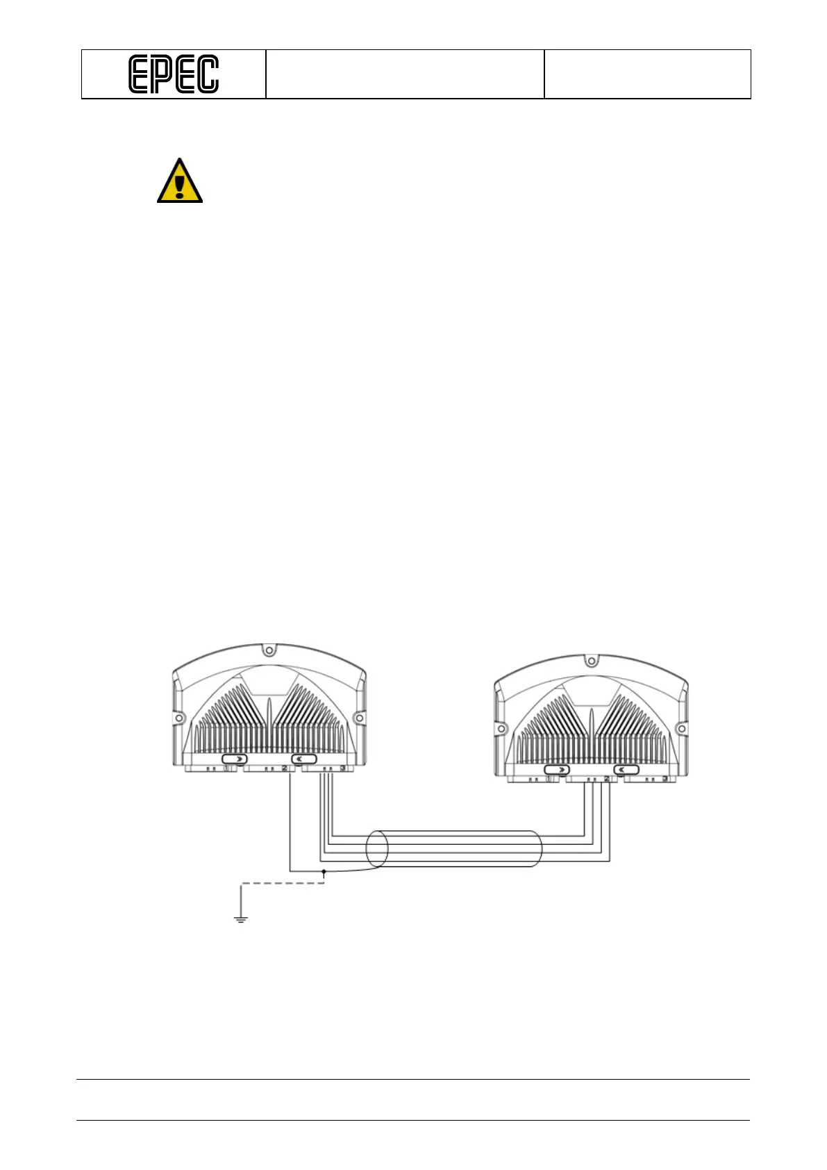
• The shield grounding must be done only in one end of the cable
Cable shield
Connection example when there is a GND pin available in the control unit: