5050 CONTROL UNIT
Technical Manual & Cabling Instructions
19.10.2012
Epec Oy reserves all rights for improvements without prior notice
Epec Oy Postiosoite/Postal address Puhelin/Phone Fax Internet
Tiedekatu 6 PL/P.O.Box 194 +358-(0)20-7608 111 +358-(0)20-7608 110 www.epec.fi
FIN-60320 Seinäjoki FIN-60101 Seinäjoki, Finland
6 INTERNAL DIAGNOSTICS
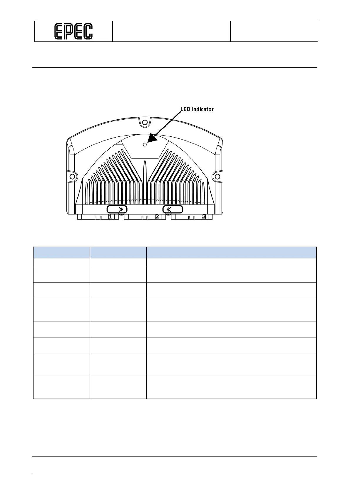
6.1 LED Indicator
The LED indicator light is situated on the top side of the 5050 according to the following figure:
The LED has green and red indicators and they indicate different operating conditions according to the
following table:
Green LED Red LED Explanation
Blinks 5
- Firmware is running, no PLCopen application
Blinks 2 times/
- Application is running and the system is OK
LED is
constantly on
- Starting / Initializing
LED is continiously on from power on until the application is
running and the I/O / CAN initializations are done.
- LED is
Control unit bootup failed or a critical firmware error while
- Blinks 2 times/
External PLCopen library controls, for example when output
controlling is disabled, so called safe state.
- Blinks 5
times/second
External PLCopen library controls, for example when system
is OK but there is short circuit in one of the outputs or other
similar error is active (depends of application)
Blinks
alternately with
red LED
Blinks
alternately with
green LED
During firmware (and application*) update, red and green
LEDs are flashed alternately.
Epec Oy reserves all rights for improvements without prior notice.