5050 CONTROL UNIT
Technical Manual & Cabling Instructions
19.10.2012
Epec Oy reserves all rights for improvements without prior notice
Epec Oy Postiosoite/Postal address Puhelin/Phone Fax Internet
Tiedekatu 6 PL/P.O.Box 194 +358-(0)20-7608 111 +358-(0)20-7608 110 www.epec.fi
FIN-60320 Seinäjoki FIN-60101 Seinäjoki, Finland
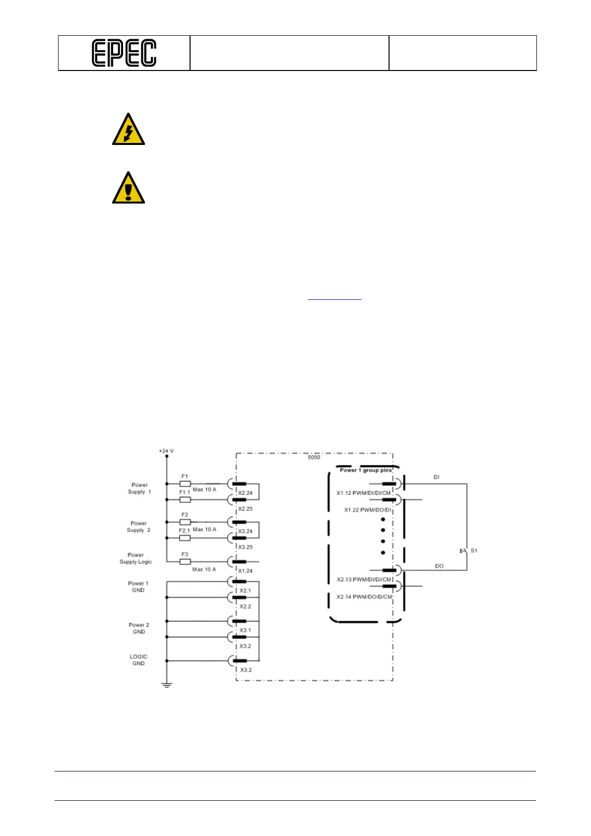
8.4.4 I/O Cabling
Closed circuit loops are always recommended and mandatory when you are using
DO or PWM pin as an input.
Closed circuit loop means that the power supply for the sensor must return to the
same power group, see the figures below.
When measuring current (mA), the sensor connected to 5050 unit’s AI/DI pin must
not be powered up before the 5050 control unit is operational. Otherwise the
sensor’s input signal is not received correctly.
• The cabling for encoders etc. is in many cases supplied together with them.
• In many cases very simple basic cable may be used, e.g. automobile R2 cable (0,5 or 1,0)
by NK Cables.
• Dimensions of the cable should be appropriate for AMP contacts (so that crimping is
possible).
• Refer to AMPSEAL table (in section
Accessories) for dimensions.
• Take extra care for protecting the cables against physical wear and damage.
• Normally, only one wire can be connected to one AMPSEAL connector pin. However, if
more than one wire has to be connected to one connector pin, it has to be connected by
branch wiring.
• Some voltage inputs use relatively low voltages.
• Consider using shielded cables for these encoders etc. especially for longer distances
to increase safety
• Using shielded cable is recommended also in joystick connections.
The following figures describe the closed loop wiring: