5050 CONTROL UNIT
Technical Manual & Cabling Instructions
19.10.2012
Epec Oy reserves all rights for improvements without prior notice
Epec Oy Postiosoite/Postal address Puhelin/Phone Fax Internet
Tiedekatu 6 PL/P.O.Box 194 +358-(0)20-7608 111 +358-(0)20-7608 110 www.epec.fi
FIN-60320 Seinäjoki FIN-60101 Seinäjoki, Finland
4 INPUT / OUTPUT SPECIFICATIONS
4.1 I/O List
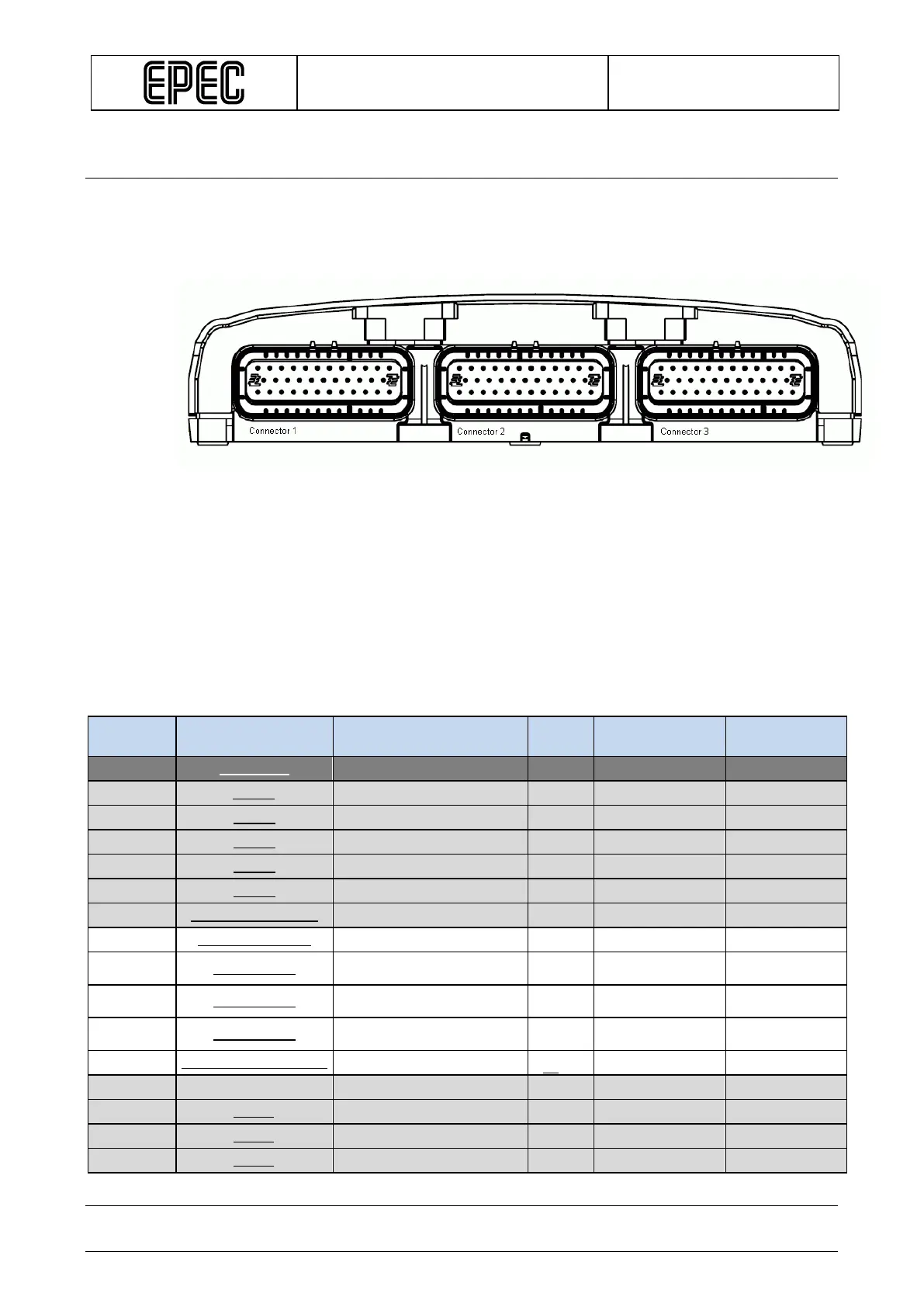
The three connectors are placed in the module according to following figure:
The following table lists the pins according their pin number. Other columns offer quick
information about the pin and links for more information.
The group column:
* P1/P2 indicates the power source for the pin
smaller case characters indicate the input groups (the pins in the same group have the
same configurations)
upper case characters indicate the output groups (the pins in the same group have the
same configurations)
I/O table
Pin
Pin type Details Group*
Current /
Information
X1.1
LOGIC GND
X1.2
CAN4H
X1.3
CAN3H
X1.4
CAN2H
X1.5
CAN1H
X1.6
CAN1H
X1.7
CAN1H TERMINATOR
X1.8
REF +10V_Type004 +10 V 250 mA
X1.9
AI/DI_Type011
2.2k +10 V / 220R GND / 47k5
GND
0..22 mA 0..10 V
X1.10
AI/DI_Type011
2.2k +10 V / 220R GND / 47k5
GND
0..22 mA 0..10 V
X1.11
DI/PI_Type003
Min input freq.
X1.12
PWM/DO/DI/CM_Type007
12k4 GND
P1 / N
Nominal current 2,5 A
X1.13
LOADER BSL For factory use only
X1.14
CAN4L
X1.15
CAN3L
X1.16
CAN2L