5050 CONTROL UNIT
Technical Manual & Cabling Instructions
19.10.2012
Epec Oy reserves all rights for improvements without prior notice
Epec Oy Postiosoite/Postal address Puhelin/Phone Fax Internet
Tiedekatu 6 PL/P.O.Box 194 +358-(0)20-7608 111 +358-(0)20-7608 110 www.epec.fi
FIN-60320 Seinäjoki FIN-60101 Seinäjoki, Finland
Note 1: A pull-up resistor is not selected.
Note 2: When pull-up resistor is selected.
Note 3: Exceeding the max values might cause damage to input.
Note 4: These parameters depend on software cycle time.
Note 5: Applies to inputs used as normal digital input. Violating this rating may lead to application
program not noticing all input state transitions.
Note 6: Overload conditions.
Note 7: Violating this rating may lead to system not recognizing all input state transitions.
Note 8: Pulse width must be greater that the software cycle time. For example with 50/50 pulse
ratio, the pulse frequency is 1 / (2*pulse width)
Note 9: tC denotes software cycle time.
Note10: Max value can be reached by 2-98% pulse ration.
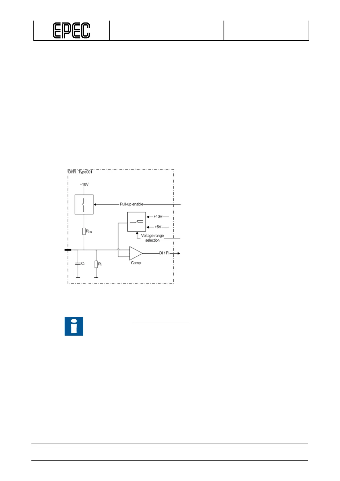
Functional block diagram
Other Information
Refer to section Connection Examples to see examples on how to connect some
external actuators or sensors when using this type of pin.