EPSON Stylus PHOTO 2100/2200 Revision B
DISASSEMBLY AND ASSEMBLY Disassembly 156
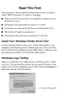
17. After facing the wider eccentric sides of the bearings on both ends of the Carriage
Guide Shafts A and B toward the printer rear and front, respectively, to increase
the distance between the Carriage Guide Shafts A and B, slightly lift the Carriage
Unit and remove the Carriage Guide Shaft A to the diagonal top left of the Printer
Mechanism.
Figure 4-79. Removing the Carriage Unit and Carriage Guide Shaft A
C A U T I O N
" When lifting the Carriage Unit, fully take care not to scratch the
Carriage Guide Shaft B.
Refer to Figure 4-79, "Removing the Carriage Unit and
Carriage Guide Shaft A".
Carriage Guide
Shaft B
Carriage
Unit
Eccentric width
(Wider)
Eccentric width
(Wider)
Carriage
Guide Shaft
A
C A U T I O N
" When removing the Carriage Guide Shaft A from the Carriage
Unit, fully use care not to lose the Oil Pad at the lower rear of the
Carriage Unit.
Refer to Figure 4-80, "Oil Pad".
Figure 4-80. Oil Pad
" Make sure that the left end of the Carriage Guide Shaft A is in
order of the Bush, Shaft Fixing Plate (Left), Plain Spring and
Leaf Spring.
Refer to Figure 4-81, "Order on Left End of Carriage Guide
Shaft A".
Figure 4-81. Order on Left End of Carriage Guide Shaft A
Oil Pad
Leaf Spring
Shaft Fixing
Plate (Left)
Bush
Plain Spring

 Loading...