Maintenance 4. Joint #1 (Replacing the Reduction Gear Unit)
108 S5 Rev.5
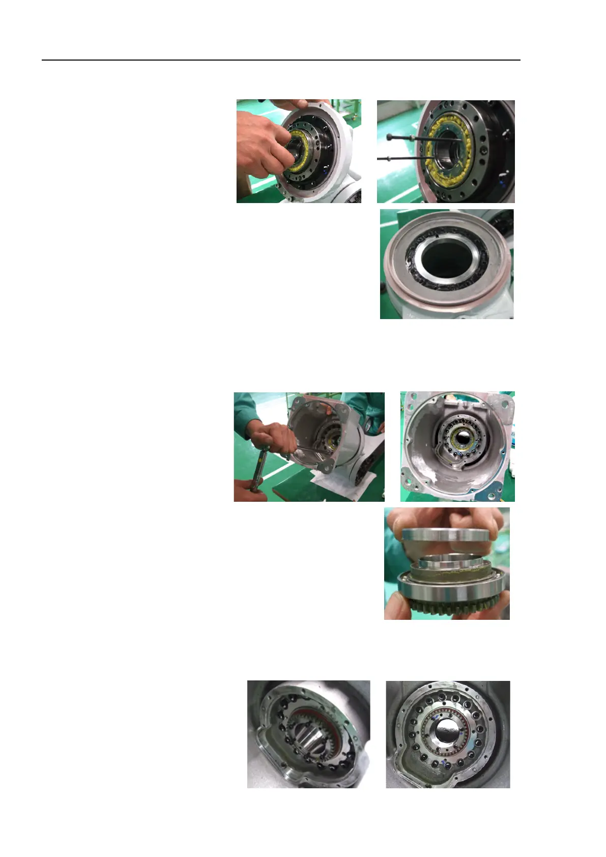
Insert the waveform generator into the circular spline and flexspline.
liquid gasket to contact surfaces of the
circular spline and flexspine of the B
ase.
Mount the circular spline and flexspline to the Base.
Press the bearing into the Joint #1 output gear.
Put a seal side of the bearing to the gear side
(Base side), and the other side to the
Mount the spacer to the Joint #1 output gear.
Mount the Joint #1 output gear to the Base.
Hexagon socket head cap bolt : 6-M3×30 (with disc spring 2H-3)
Tightening torque : 2.25 N·m (0.23 kgf·m)

 Loading...


