Maintenance 7. Option Parts Replacement Procedures
42 RC700 Series Maintenance Rev.3
WARNING
■
Before installing the Control Unit or Drive Unit with this option, always make
sure that the main power
of the Controller is turned OFF and that the power plug
. Performing any installation procedure while the main power
is ON or the high voltage charged area is not
discharged completely is extremely
hazardous and may result in electric shock and/or cause serious safety
problems.
■
When opening the front side, make sure to disconnect the power plug.
Touching the power supply terminal block inside the Control
Unit or Drive Unit
while the power supply is ON is extremely hazardous and may result in electric
shock and/or cause serious safety problems.
- Be careful not to damage the cables.
- Be careful not to drop any screws into the Controller.
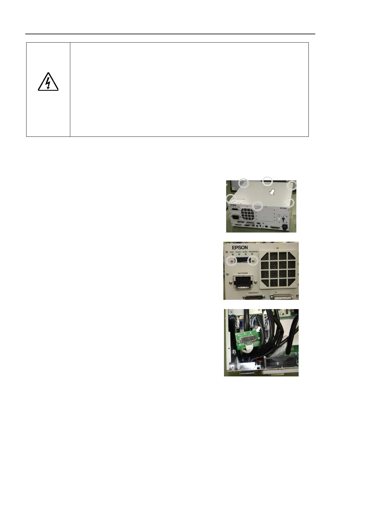
Remove the Top Cover Mounting
×6)
Remove the screws fixing the seven segment
display.
Controller front side: Mounting screw×2)
Remove the LED/7 segment board from the
Controller.
-A:
The LED/7 segment board has the ferrite code
8.8.2 DMB-LED Board (RC700-
If the LED DISPLAY PLATE is installed with
“
wall mounting with the front side up” described
in the step (7) below, the cable which passes the
ferrite core will be an opposite direction.
Remove the latch of the ferrite core and change
the cable direction,
and then install the ferrite

 Loading...


