2. Installation
212 RC700 / RC90 Option Fieldbus I/O Rev.14
LED Description
LED state represents the states of the fieldbus I/O board.
Run LED
No network participation, timeout state (no power)
Participating, normal operation
Major fault (FATAL error)
Error LED
No error detected (no power)
Major fault (Exception or FATAL event)
CRC error (temporary flickering)
Station Number or Baud rate has changed since startup
(flashing)
Wiring
The CC-Link connector is a 5-pin open connector. Use the connector attached to the
module for wiring.
Terminal name for each pin
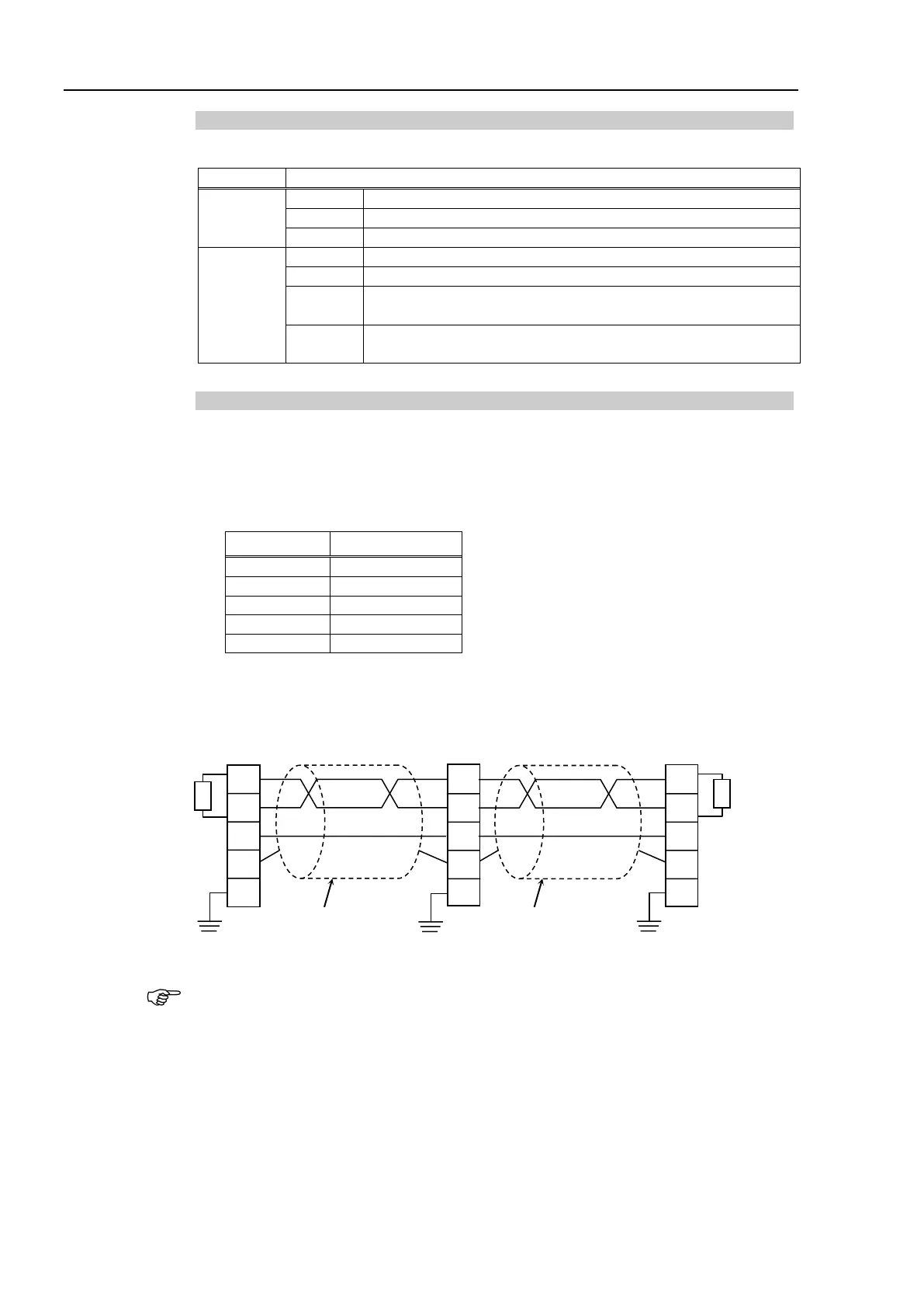
Connect the CC-Link master module and the CC-Link slave module as follows.
DA
DB
DG
SLD
FG
Terminating
Resistor
Master Station
DA
DB
DG
SLD
FG
DA
DB
DG
SLD
FG
CC-Link
Module
Twisted-pair Cable
with Shield
Robot System
CC-Link Module
Terminating
Resistor
Twisted-pair Cable
with Shield
Prepare the cable for CC-Link Ver.1.10 sold in the market as a communication cable.
Install terminating resistors at both ends of the network.
Use the terminating resistors attached to the CC-Link master station.
Make sure to disconnect the connectors only after turning OFF the power supply of
the specific station.
Connect the shield wire for CC-Link to the “SLD” of each unit and ground the both
ends via “FG”.