4. Troubleshooting (PROFIBUS DP)
308 RC700 / RC90 Option Fieldbus I/O Rev.14
4.2.3 Procedures for Examining Possible Causes
4.2.3.1 Connection Problem (Disconnected Terminating Resistors, Cable
Disconnection, Disconnected Connector, and Disconnected Signal Wire)
(1) Ensure that two terminating resistors are connected to both ends of the network.
(2) Turn OFF all device power supplies.
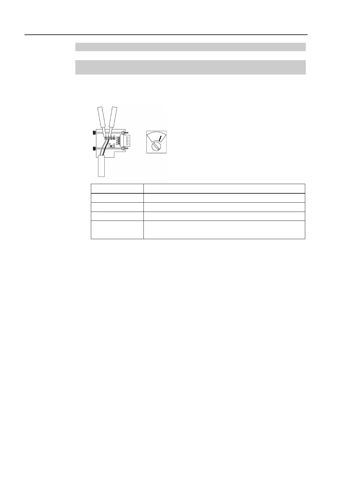
(3) Measure resistance between A1 and B1 wires of the absent slave using the tester.
Tester
Measure resistance between signal wires with tester.
Ω
Ω
Three or more terminating resistors on one network
Ω
Over 120 Ω Error (cable disconnection, disconnected signal wire, one or
zero terminating resistor)
(4) How to find the trouble point:
- Remove the terminating resistor on one end of the network.
(The resistance at the point where the terminating resistor is connected is 220 Ω.)
- Measure resistance at branch taps of all units.
- The trouble point is where resistance changes from 220 Ω.
- After finding the trouble point, verify the connector and cable conditions.