2. Installation
200 RC700 / RC90 Option Fieldbus I/O Rev.14
2.4 CC-Link
2.4.1 Installing CC-Link Slave Board
WARNING
Make sure that the power is turned OFF before installing/removing any boards
or connecting/disconnecting any cables. Installing/removing any boards or
connecting/disconnecting any cables with the power ON is extremely hazardous
and may result in electric shock and/or malfunction of equipment.
CAUTION
Pay attention to the followings in order to prevent the the connecter from coming
off.
1. Use the connectors attached to the board.
2. Insert the connectors all the way seated.
3. Fix the cables at proper positions in order not to put a load on the
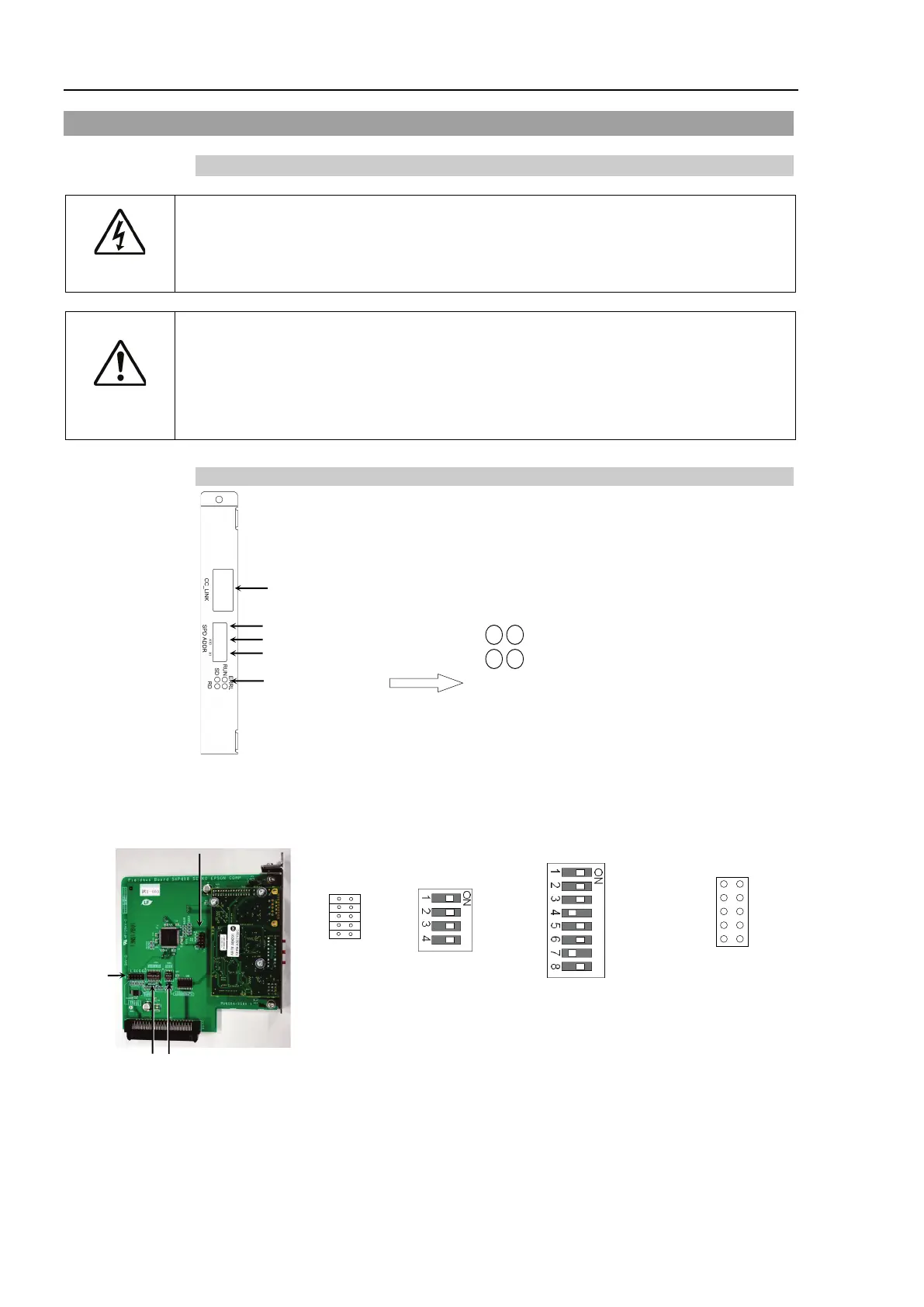
Appearance
Status Display LED
Baud Rate Configure Switch
Station Configure Switch (× 10)
Station Configure Switch (× 1)
CC-Link Connector
SD LED : Data transmission
status display
RUN LED : Offline status
display
RD LED : Data reception status
display
ERRL LED : Error status display
The Fieldbus slave board is configured as follows at shipment.
SW1
SW2
SW3
SW4
SW5
SW6
SW7
SW8
IRQ5
IRQ7
IRQ10
IRQ11
IRQ15
JMP1
JP1
JP2
JP3
JP4
JP5
1 2
All Open All ON Fixed as above All Open