4. Troubleshooting (PROFIBUS DP)
RC700 / RC90 Option Fieldbus I/O Rev.14 291
4.2 PROFIBUS DP Troubleshooting
Exclusion
Every system has its special environment, conditions, specifications, and usages. This
guide is provided as a general reference for troubleshooting a PROFIBUS DP network.
Every effort has been made to ensure the information is accurate. However, we do not
guarantee the complete accuracy of the information and thus we decline any liability for
damages or costs incurred by the use of this troubleshooting.
Before examining a problem on the network, please ensure that your established
PROFIBUS DP system satisfies network specifications. (Refer to this troubleshooting and
the section 2.2.2 PROFIBUS DP Network Construction.)
Tools
Prepare the following tools for troubleshooting.
Philips screwdriver
Flat-blade screwdriver
Tester
4.2.1 Examining a Problem
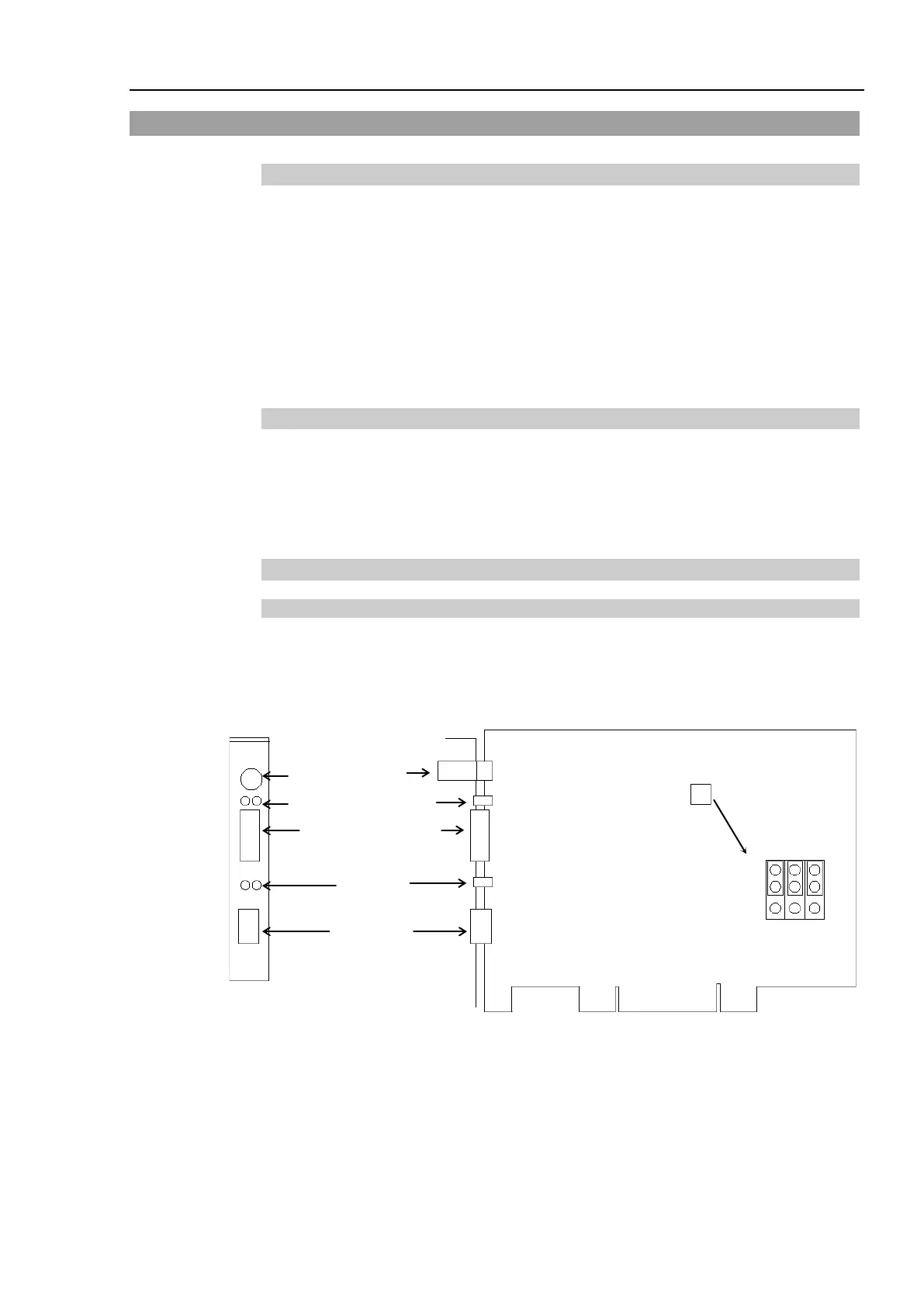
4.2.1.1 Scanner Board Diagnostic LEDs
The PROFIBUS DP board used with EPSON RC+ has two status display LEDs. The
layout of the LEDs is shown in the following figure.
PCU-DPIO
4-pin Terminal
Watchdog Port
(Do not use this port.)
Jumper for Board Address Setting
The Communication Status LED is on the left and the Physical Error LED is on the right
seen from the rear panel.
The Communication Status LED is referred to as the ST LED (ST) in this section.
The Physical Error LED is referred to as the BF LED (BF) in this section.