4. Troubleshooting (DeviceNet)
258 RC700 / RC90 Option Fieldbus I/O Rev.14
4.1.1 Examining a Problem
4.1.1.1 Scanner Board Diagnostic LEDs
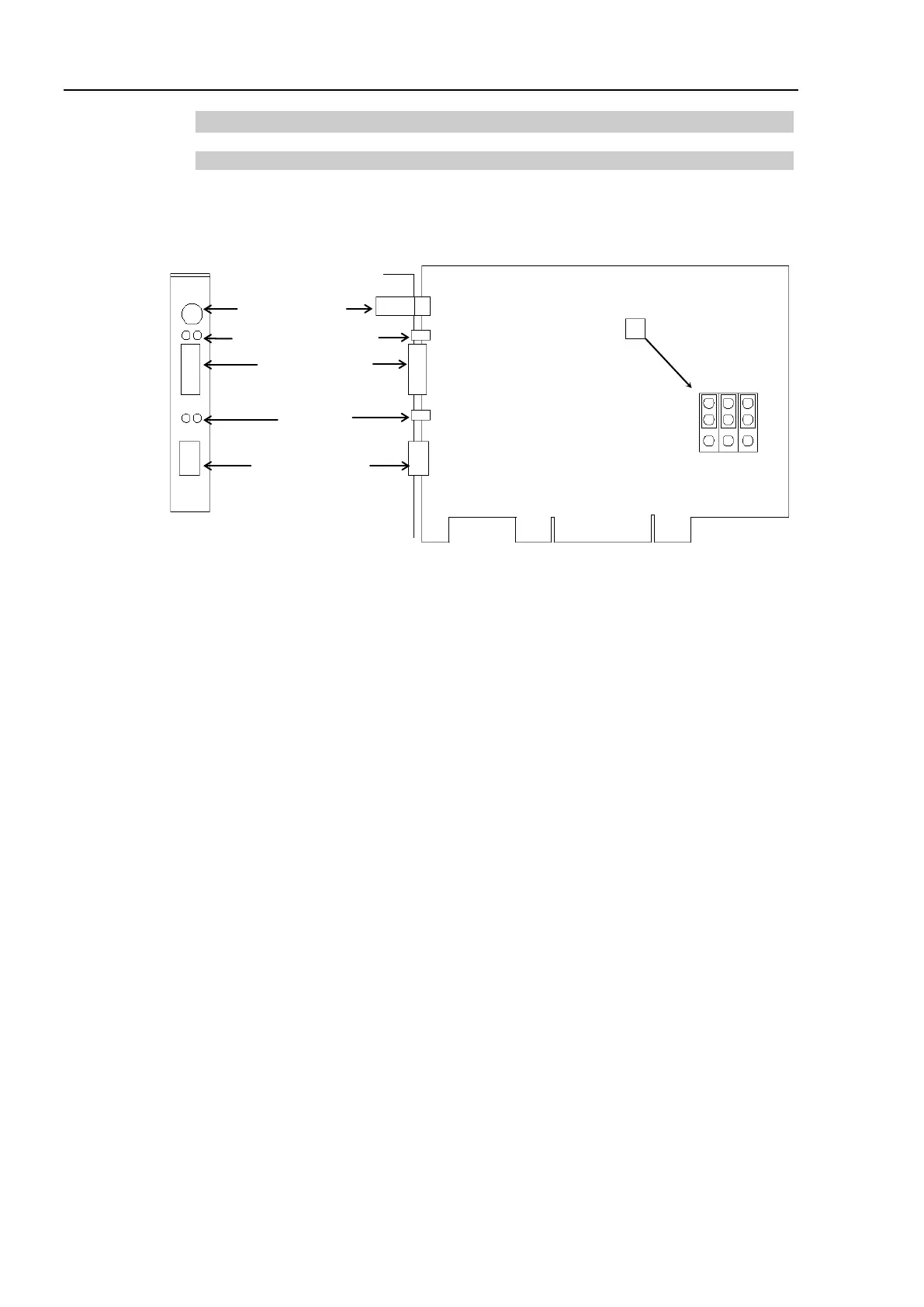
The DeviceNet master board used with EPSON RC+ has two status display LEDs. The
layout of the LEDs is shown in the following figure.
PCU-DVNIO
4-
pin Terminal
Watchdog Port
(Do not use this port.)
Jumper Pin for Board Address Setting
The Module/NetWork LED is on the left side and the IO LED is on the right side seen
from the rear panel. These LED names are used in applicomIO Console application and
this manual. Only in this troubleshooting section, general names of the status display of
the DeviceNet device are used.
The Module/NetWork LED is referred to as the Network Status (NS) in this section.
The IO LED is referred to as the Module Status LED (MS) in this section.