2. Installation
186 RC700 / RC90 Option Fieldbus I/O Rev.14
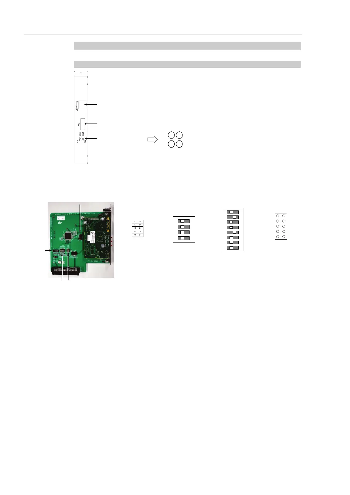
2.3.5 Installing EtherNet/IP Slave Board
Appearance
Status Display LED
Configure Switch
EtherNet/IP Connector
ACT LED : Link status display
LNK LED : Communication packet
reception or transmission status
display
NS LED : Network status display
MS LED : Module status display
The Fieldbus slave board is configured as follows at shipment.
SW4
SW3
SW2
SW1
DSW2
ON
1234
SW8
SW7
SW6
SW5
SW4
SW3
SW2
SW1
12345678
ON
DSW1
IRQ15
IRQ11
IRQ10
IRQ7
IRQ5
JMP1
JP5
JP4
JP3
JP2
JP1
1 2
All Open All ON Fixed as above All Open