4. Troubleshooting (EtherNet/IP)
318 RC700 / RC90 Option Fieldbus I/O Rev.14
4.3 EtherNet/IP Troubleshooting
Exclusion
Every system has its special environment, conditions, specifications, and usages. This
guide is provided as a general reference for troubleshooting a EtherNet/IP network. Every
effort has been made to ensure the information is accurate. However, we do not guarantee
the complete accuracy of the information and thus we decline any liability for damages or
costs incurred by the use of this troubleshooting.
Before examining a problem on the network, please ensure that your established
DeviceNet system satisfies network specifications. (Refer to this troubleshooting and the
section 2.3.2 EtherNet/IP Network Construction.)
4.3.1 Examining a Problem
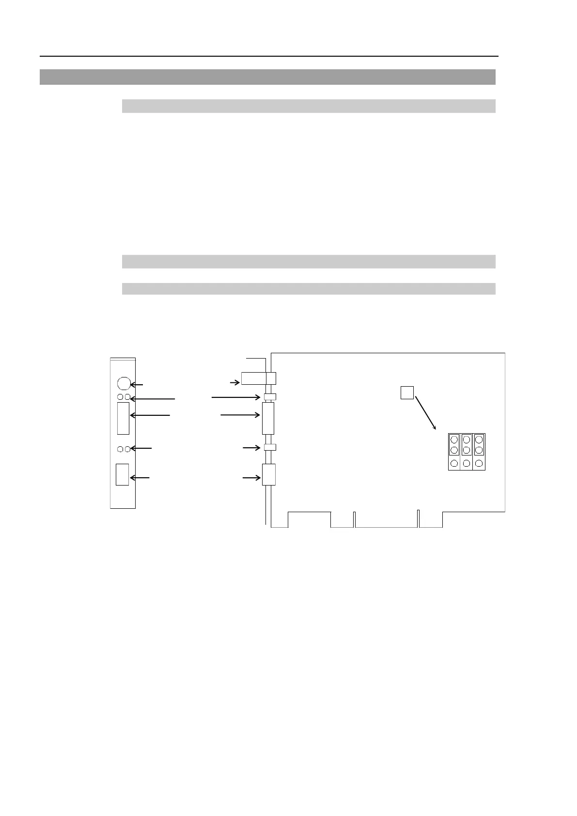
4.3.1.1 Scanner Board Diagnostic LEDs
The EtherNet/IP board used with EPSON RC+ has two status display LEDs. The layout
of the LEDs is shown in the following figure.
PCU-ETHIO
C0 C1 C2
JP1
JP1
0
1
D-Sub 9 pin
(Not in use)
Status Display LED (2)
EtherNetI/P Connector
4-pin Terminal
Watchdog Port
(Do not use this port.)
Jumper for Board Address
LED (2)
(Not in use)
The Module/NetWork LED is on the left and the IO LED is on the right seen from the rear
panel. These LED names are used in applicomIO Console application and this manual.
Only in this troubleshooting section, general names of the status display of the DeviceNet
device are used instead.
The Network Status LED is referred to as the NS LED (NS) in this section.
The Module Status LED is referred to as the MS LED (MS) in this section.