4. Troubleshooting (PROFIBUS DP)
RC700 / RC90 Option Fieldbus I/O Rev.14 317
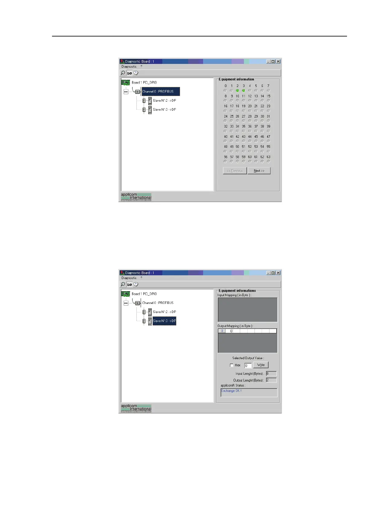
(4) When you click the <I/O> icon, the window changes as shown below.
The status of each slave device is shown in the right side of the window.
A green circle indicates that the communication of the corresponding device is normal,
and a red circle indicates that there is a communication error.
A gray circle indicates that the corresponding device does not exist.
(5) When you select the slave from the device tree in the left side of the window, the
window changes as shown below.
The input and output statuses of the selected device are shown in the right side of the
window.
If you want to change output data, click the bite number you want to change in
[Output Mapping]. Then, enter a value in [Write] in the “Selected Output Value” and
click <Write>.