2. Installation
RC700 / RC90 Option Fieldbus I/O Rev.14 211
2.4.2 Installing CC-Link Slave Module
WARNING
■
Make sure that the power is turned OFF before installing/removing any
modules
connecting/disconnecting any cables. Installing/removing any boards or
connecting/disconnecting any cables with the power ON is extremely hazardous
and may result in electric shock and/or malfunction of equipment.
CAUTION
■
followings in order to prevent the the connecter from coming
1. Use the connectors attached to the module.
2. Insert the connectors all the way seated.
3. Fix the cables at proper positions in order not to put a load on the
connectors.
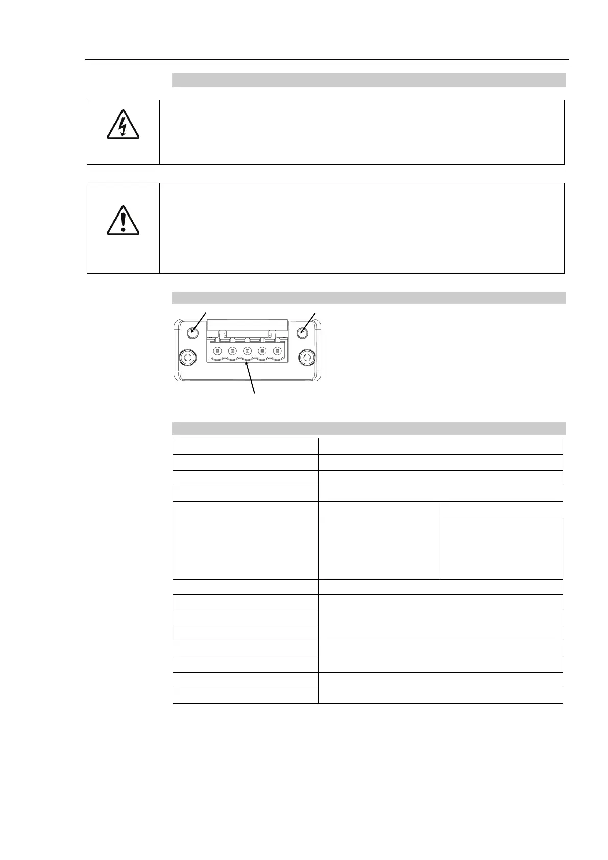
Appearance
Run LED
CC-Link Connector
Error LED
Specifications
Items Specification
156 k, 625 k, 2.5 M, 5 M, 10 M (bps)
Transfer Distance
5 M (bps)
2.5 M (bps)
625 k (bps)
160 m
400 m
900 m
Dedicated cable supporting CC-Link Ver.1.10
1 to 4 station(s) (Remote device station)
Master Station’s Handshake