2. Installation
226 RC700 / RC90 Option Fieldbus I/O Rev.14
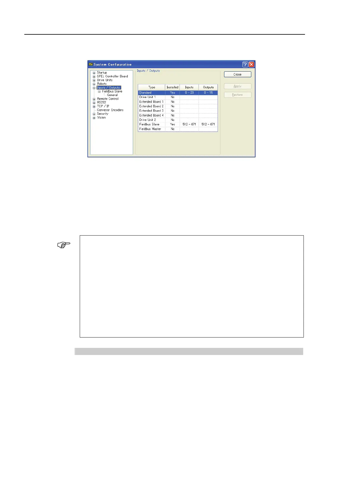
8. Select [Setup]-[System Configuration] and display the [System Configuration] dialog
box.
9. Select [Inputs / Outputs].
10. Confirm that the following items are displayed in “Fieldbus slave”.
Inputs : 512 – ( 512 + Changed number of input (Bits) )
Outputs : 512 – ( 512 + Changed number of output (Bits) )
In this example, Input byte is 20 bytes (160 bits) and 512-671 is displayed in Inputs.
Also, Output byte is 20 bytes (160 bits) and 512-671 is displayed in Outputs.
11. Click <Close>.
When setting this option to the PROFINET IO Controller (Master), configure as
below.
The Robot Controller includes 16 pseudo I/O slots. In these slots, add 1 to 32 bytes
input modules, output modules.
Make sure to add the output modules first, and then, add the input modules.
<Example> Input: 40 bytes / Output: 48bytes (set in the RC+ window)
Slot 1 : 32 bytes output module
Slot 2 : 16 bytes output module
(Set 48 bytes in total for the Output.)
Slot 3 :32 bytes input module
Slot 4 : 8 bytes input module
(Set 40 bytes in total for the Input.)
Electronic Information File (GSDML file)
A GSDML file is provided for the PROFINET slave board network configuration.
The file is located in the following folder where EPSON RC+ 7.0 is installed.
\EpsonRC70\Fieldbus\PROFINET