4. Troubleshooting (DeviceNet)
RC700 / RC90 Option Fieldbus I/O Rev.14 273
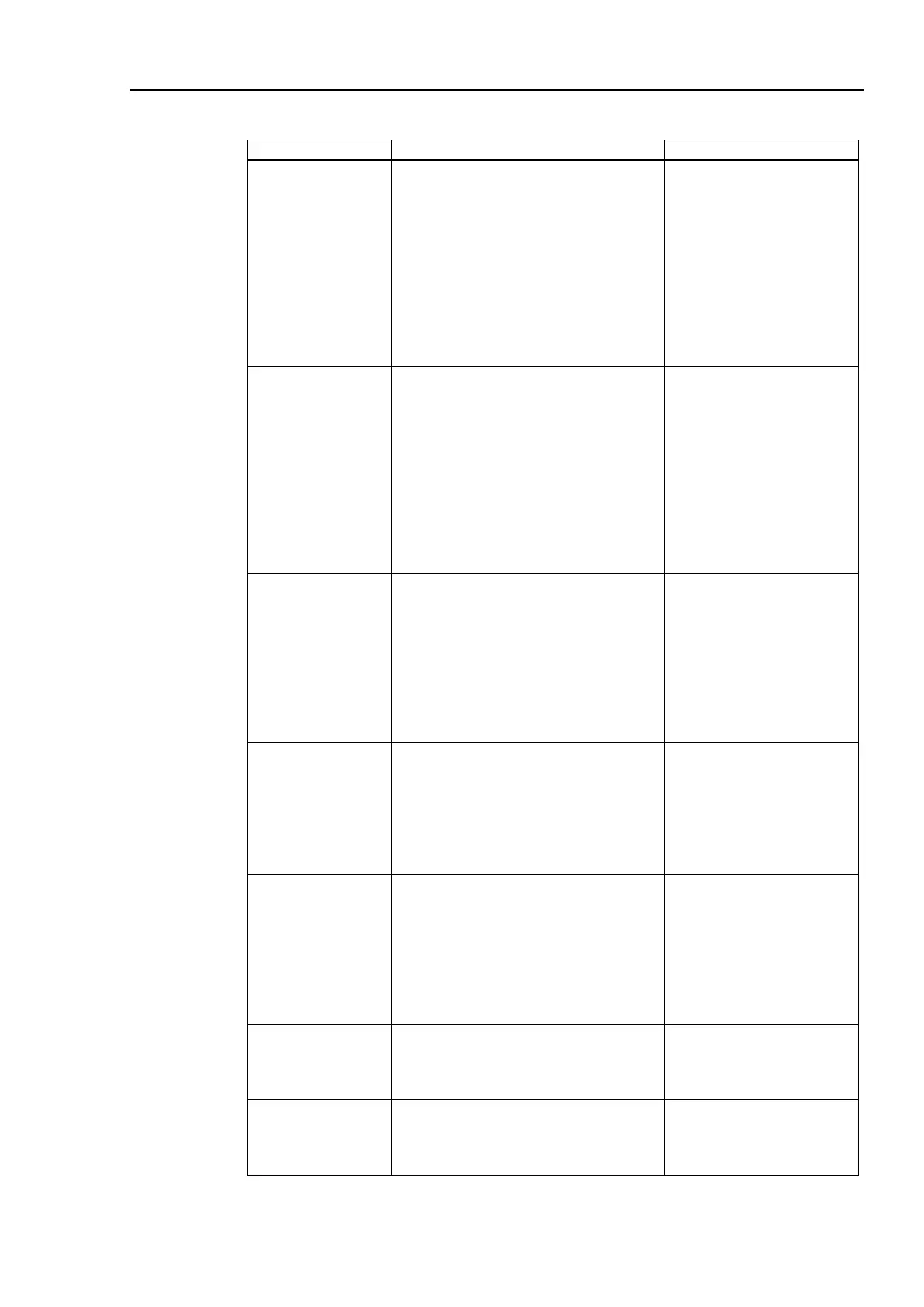
♦ Causes of Error
configuration
(1) Start applicomIO Console
application and check that the
configuration has no difference
with the network condition.
(2) Check that
were written in flash.
(3)
Check that the network load is
within allowable range.
For details, refer to the section
4.1.3.6 EPSON RC+ Master
Change the configuration.
terminating
resistors
Cable
disconnection
Disconnected
connector
Disconnected
signal wire
(1) Check that terminating resistors
are connected to both ends of the
network.
(2) Measure resistance between signal
wires with communications power
supply OFF.
→ Normal: 50 to 70Ω
Measuring point: Connection of the
trouble unit
For details
, refer to the section
4.1.3.1 Connection Problem.
How to find
point:
resistor on one
end of the
network. The trouble
point is where resistance
changes from 120 Ω.
Loose signal
wire
Check for the connection of connectors
and signal wires.
→
The connectors and signal wires
should be firmly connected.
Checkpoint: all nodes and all branch
taps
For details, refer to the section
4.1.3.2 Loose Connector and Signal
and signal wires again.
communications
power supply
Measure voltage of communications
power supply at the unit with a trouble.
→
Normal: 11V or more between V+
and V-
If the voltage is 11 to 14 V, the unit
is a possible cause. Fix the problem
power supply.
Calculate the current
capacity of the cable and
add
power supplies.
(external cause)
Check the noise intrusion via the
following paths (1) to (3).
(1) Noise via DRAIN (FG)
(2)
Induced noise via communication
cable
(3) Communications power supply
→
For details, refer to the section
4.1.3.3 Noise Intrusion.
against noise.
Replace the broken unit with a new
one.
→ Verify whether the problem is
new one.
identified.
Identify the trouble point by dividing
the network.
→
For details, refer to the section
4.1.3.4 Broken Unit Examination.