4. Troubleshooting (DeviceNet)
RC700 / RC90 Option Fieldbus I/O Rev.14 285
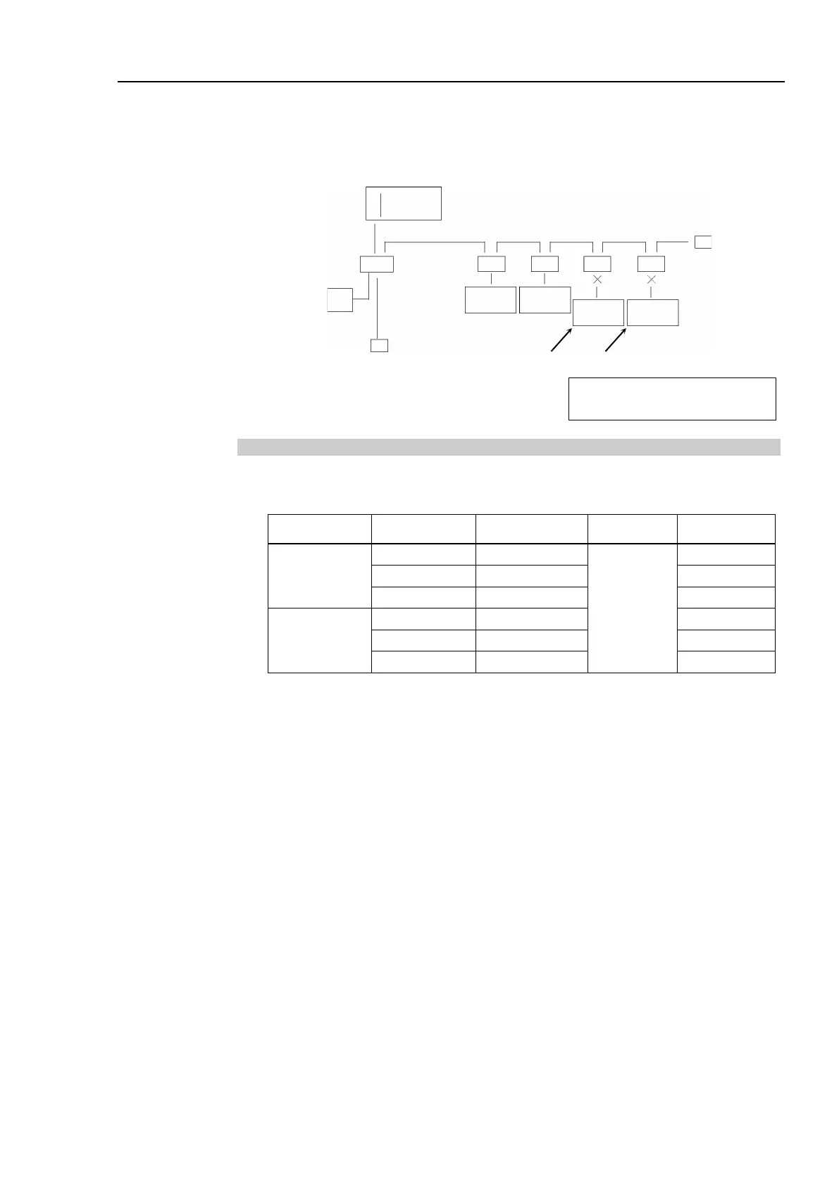
(2) Separate each slave from the network
Check for each slave. The trouble point is where error condition changes into normal
condition.
PLC
Slave
Branch Tap
Communications
Power Supply
Terminating
Resistor
Branch Tap
Slave
Slave
Master
Slave
Second First
Separate slaves one by one from
the network.
Terminating
Resistor
4.1.3.5 Network Configuration and Specifications
(1) Maximum Network Length and Drop Line Length
Check that the cables used on the network meet the following specifications.
Type Baud Rate
Thick Cable
6 m
Thin Cable
(2) Terminating Resistor
Ensure that two terminating resistors are connected to both ends of the network (trunk
line). The terminating resistor should be 121 Ω 1/4 W.
(3) Cable and Branch Tap
The cables and branch taps should meet the DeviceNet specifications.
(4) Communications Power Supply
The communications power supply should be dedicated to DeviceNet.
Do not share the communications power supply with I/O devices. *
* Noise due to load on/off may affect DeviceNet communications via the
communications power supply.
(The noise causes remote I/O communication error, Busoff detection, and broken
unit.)