2. Installation
RC700 / RC90 Option Fieldbus I/O Rev.14 19
Terminating Resistor
To reduce reflections of communication signal, terminating resistors should be attached on
both ends of the trunk line. For DeviceNet, nodes have no terminating resistor on the ends.
Attach 121 Ω +/-1%, 1/4W terminating resistors between the signal wires (CAN-H and
CAN-L) of the trunk line cable. Some commercially available T-branch taps and
connectors can accept terminating resistors. Molded terminating resistors with connectors
are also available to attach to environment-resistant T-branch taps and connectors.
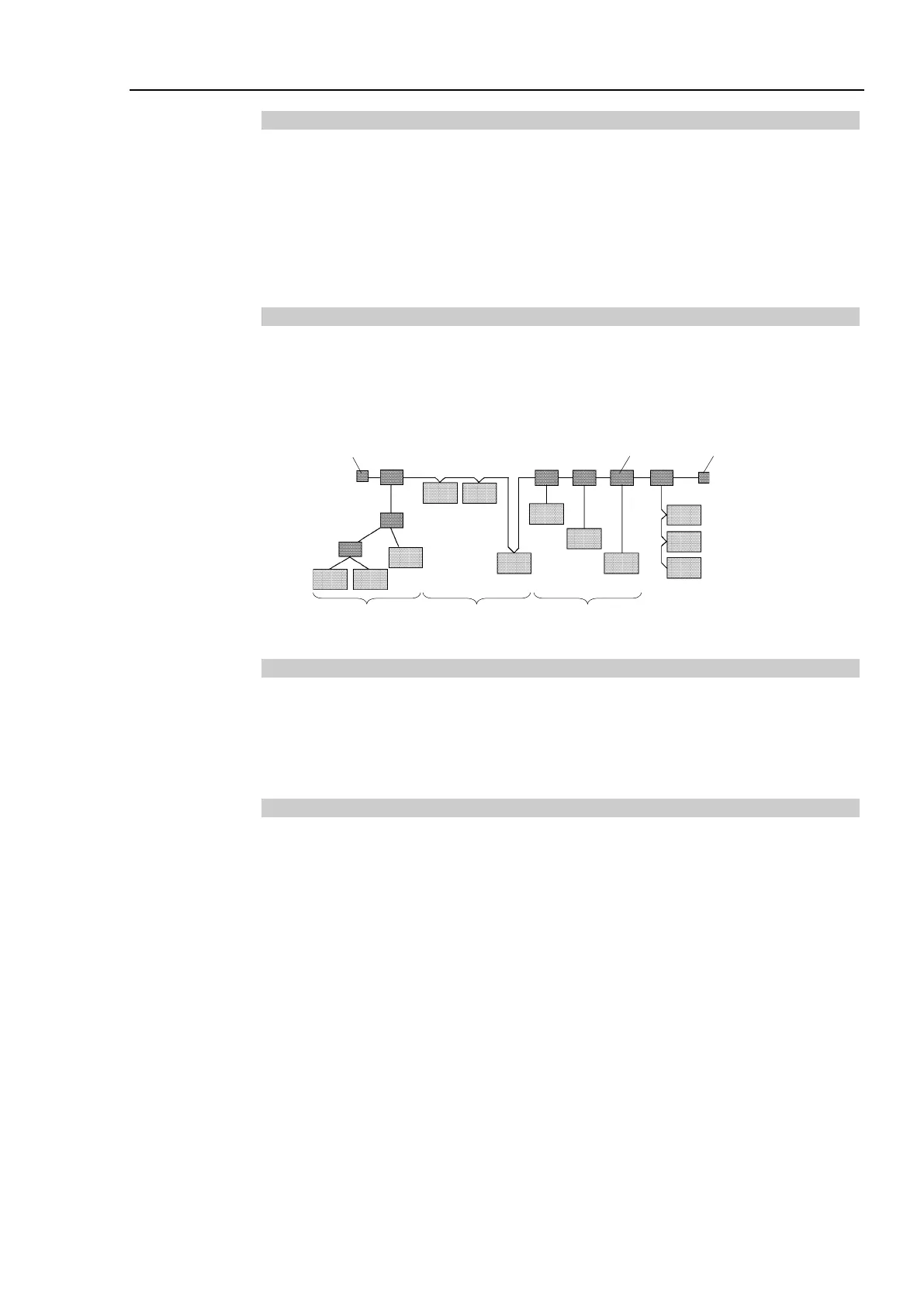
Node Connection
Nodes can be connected to a DeviceNet network by the following topologies: tree, multi-
drop, T-branch, daisy chain. For tree topology, there is no limitation of daisy chain layer
but drop line length is limited. For details of drop line length, refer to the following
section Drop Line Length.
Daisy Chain
Terminating
Resistor
Terminating
Resistor
Branch Tap
Trunk Line
T-branch Multi-drop Tree
Communications Power Supply
DeviceNet supplies 24V DC communications power to each node via 5-wire cables. You
can install the communications power supply at any location in the DeviceNet network.
Although the power can be shared to the node internal circuit power supply and I/O power
supply, it is recommended to use a dedicated communications power supply.
Shield Ground of Signal Wire
Ground the DeviceNet network at one point with 100 Ω or less.
As a noise countermeasure, you can leave the network ungrounded.
For details, refer to 4. Trouble shooting.