2. Installation
86 RC700 / RC90 Option Fieldbus I/O Rev.14
The following figure illustrates wiring sample.
Station 1 Station 2
RxD/TxD-P (3)
DGND (5)
VP (6)
RxD/TxD-N (8)
(3) RxD/TxD-P
(5) DGND
(6) VP
(8) RxD/TxD-N
Shield
Protective Ground Protective Ground
PROFIBUS cables are produced by a variety of manufacturers.
For details of the PROFIBUS cables, see PROFIBUS International’s website
(http://www.profibus.com/).
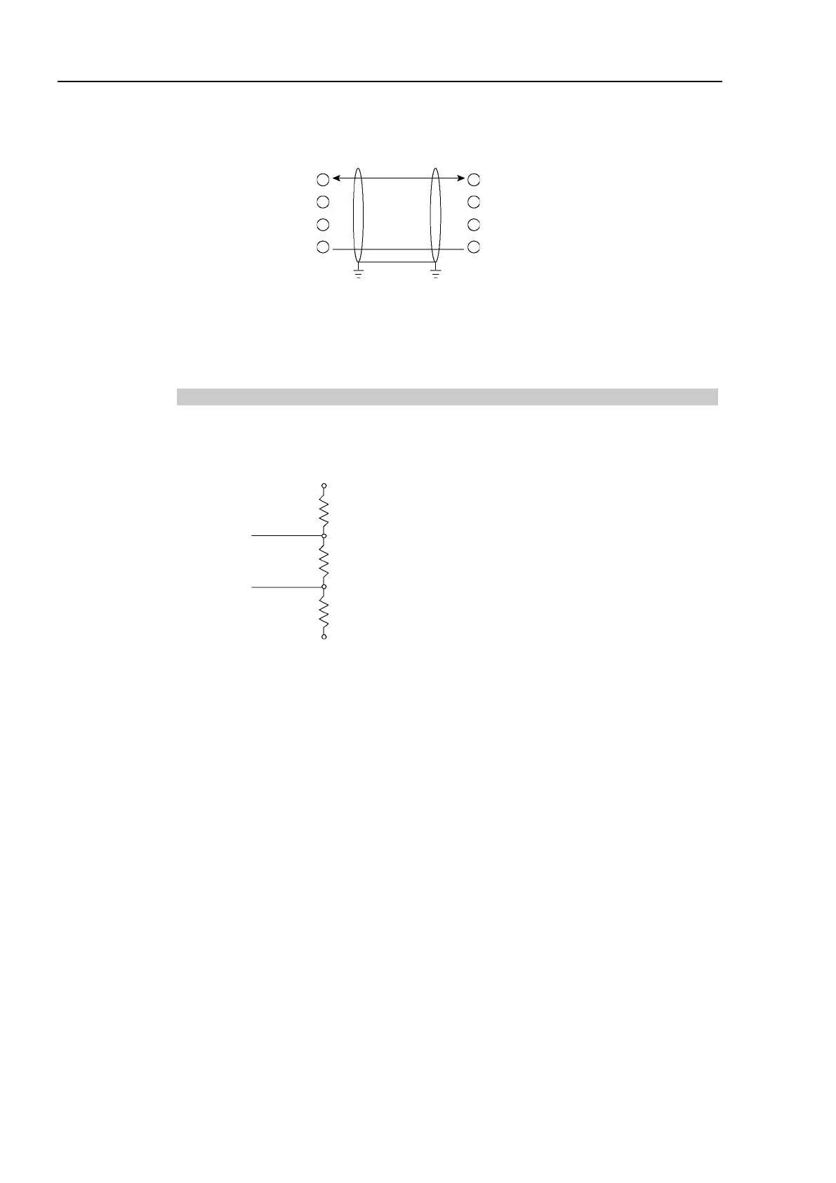
Terminating Resistor
To reduce reflections of communication signal, terminating resistors should be attached on
both ends of each segment. Attach the terminating resistor as shown below.
VP (6)
390 Ω
RxD/TxD-P (3)
220 Ω
RxD/TxD-N (8)
390 Ω
DGND (5)
Data Line B
Data Line A
Some commercially available PROFIBUS 9-pin D-Sub connectors have functions of
terminating resistor and they can enable/disable the terminating resistors. (Example:
Woodhead MA9D00-32)
Molded terminating resistors with connector that can be attached to environment-resistant
M12 connector are also available.