SC-F9200 Series Revision B
DISASSEMBLY & ASSEMBLY Disassembly and Assembly Procedure 121
SE Group Confidential (Related Staff Only)
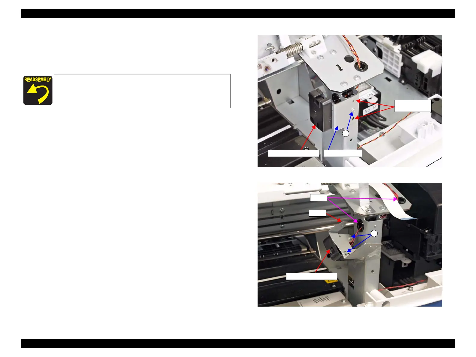
8. Remove the screw that secures the mounting plate.
A) Silver M3x8 S-tite screw with built-in washer: 1 pcs
9. Lift the mounting plate to disengage the hook and remove the Front Cover R
Sensor together with the mounting plate.
10. Remove the two screws, and remove the Front Cover R Sensor from the mounting
plate.
B) Silver M3x8 P-tite screw with washer: 2 pcs
11. Pull out the cable through the holes on the frame, and remove the Front Cover R
Sensor.
Figure 3-42. Removing the Mounting Plate
Figure 3-43. Removing the Front Cover R Sensor
When installing the mounting plate, insert its positioning hole
over the dowel on the main body frame.
Route the sensor cable through the cable guide correctly.
Front Cover R Sensor
Positioning holes
and dowels
Mounting plate
A
B
Front Cover R Sensor
Holes
Hook

 Loading...


